В. Белотелов
«Квант» №1, 2010
В последнее время идея создания оптических компьютеров приобретает все большую популярность. Она подкрепляется, с одной стороны, неиссякающим стремлением к все большим скоростям вычислений, а с другой стороны — удивительными возможностями современных технологий. Для того чтобы обрабатывать и передавать информацию с помощью света, т. е. с помощью фотонов, надо научиться эффективно управлять ими. Хотя электрического заряда у фотонов нет, но наличие поляризации — ориентации их электромагнитного поля — дает определенную надежду на успех.
Прежде всего перенесемся в конец XIX века, в лабораторию великого английского физика Майкла Фарадея — ведь именно оттуда берет исток наша история.
«Намагнитить луч света и осветить магнитную силовую линию»
Разнообразные физические явления, связанные с магнитными и оптическими свойствами среды, в течение многих столетий изучались независимо. Свет сопровождает человечество с момента его зарождения, а магнетизм известен с древних времен. Однако только в 1845 году М. Фарадей впервые провел эксперименты, доказавшие связь между этими явлениями. Отчасти это связано с тем, что в обычных условиях магнитооптические эффекты весьма малы и для их открытия требовалась физическая интуиция гения. Удивительно, что это произошло в то время, когда не было ясного понимания ни природы магнитных свойств, ни природы оптических явлений и когда еще не были сформулированы уравнения Максвелла.
«Я уже давно придерживался мнения, что различные формы и силы материи настолько близки и родственны, что могут превращаться друг в друга. Это твердое убеждение побудило меня произвести много изысканий с целью открыть связь между светом и электричеством. Однако результаты оказались отрицательными…» — так сам Фарадей комментирует свои опыты.
«Эти безуспешные изыскания не могли поколебать моего твердого убеждения, основанного на научных соображениях. Поэтому я недавно возобновил исследование на очень тонких и строгих началах, и в конце концов мне удалось намагнитить и наэлектризовать луч света и осветить магнитную силовую линию.»
В словах «намагнитить луч света» подразумевается вызываемое магнитным полем вращение плоскости поляризации света — магнитооптический эффект Фарадея. Кроме того, обращают на себя внимание и слова «осветить магнитную силовую линию», намекающие на возможное обратное влияние света на магнетизм. В опытах Фарадея такого явления обнаружено не было, но эти слова указывают на то, что великий физик фактически предсказал и его. Влияние света на магнитные свойства вещества было теоретически доказано гораздо позже. В 1960 году советский физик Л. П. Питаевский показал, что свет, обладающий круговой поляризацией, способен намагнитить среду, которую он освещает. Эффект получил название обратного эффекта Фарадея.
Хотя обратный эффект Фарадея тоже имеет большую практическую значимость, в этой статье речь пойдет только о прямом магнитооптическом эффекте, ведь наша цель — управлять светом, используя магнитное поле.
Спин и поляризация фотонов
Напомним, что можно говорить о естественном, т. е. неполяризованном, свете, а также можно выделить три основные состояния поляризации: плоская, круговая и эллиптическая поляризации. В общем случае поляризованный свет обладает эллиптической поляризацией, т. е. траектория проекции конца вектора напряженности электрического поля волны на плоскость, перпендикулярную направлению ее распространения, является эллипсом. Наибольший практический интерес представляют два крайних случая эллиптической поляризации: линейная поляризация, когда эллипс вырождается в отрезок, и круговая поляризация, при которой эллипс превращается в окружность.
С квантово-механической точки зрения, понятие поляризации света связано с наличием у фотона спина. Фотоны, как частицы с нулевой массой покоя, могут находиться в двух состояниях со значениями момента импульса ±ћ (ћ — постоянная Планка), направленного вдоль импульса фотона. Такие фотоны обладают круговой поляризацией: левой, когда квантовое число m = +1, или правой, когда m = –1. Эллиптически поляризованные фотоны находятся в состоянии, которое складывается из состояний с m = ±1; при линейной поляризации суперпозиция этих состояний такова, что средняя проекция момента на направление импульса равна нулю.
Эффект Фарадея
У свободного фотона состояния с m = +1 и m = –1 имеют одинаковые энергии (частоты). В квантовой механике такую ситуацию называют вырождением. Снять вырождение можно при помощи внешнего магнитного поля, направленного вдоль волнового вектора (предполагается, что фотон распространяется в среде с показателем преломления n). В магнитном поле компоненты с m = ±1 будут распространяться с разными фазовыми скоростями:

Здесь c — скорость света, n — показатель преломления среды, a Q — специальный магнитооптический параметр. В немагнитных средах параметр Q пропорционален магнитному полю и в не очень больших полях (магнитная индукция не превышает 200–300 мТл) имеет типичное значение порядка 10–6–10–4. В ферромагнитных материалах этот параметр отличен от нуля даже в отсутствие поля и достигает величин 10–3–10–1. Он определяется внутренним магнитным полем, которое создается атомами и ионами кристаллической решетки магнетика.
Но с фазовой скоростью непосредственно связан показатель преломления среды:

В результате получается, что в магнитной среде волны, поляризованные по часовой стрелке и против нее, преломляются по-разному — возникает явление циркулярного двойного лучепреломления, или гиротропии среды. Явление гиротропии связано с эффектом Зеемана, т. е. с расщеплением линий поглощения света в магнитном поле. Под действием силы Лоренца резонансные частоты вращения электронов по левому и правому кругу смещаются в различные стороны относительно первоначального значения собственной частоты. Это, в свою очередь, и приводит к различию показателей преломления для волн, поляризованных по правому и по левому кругу. Экспериментально при этом наблюдается эффект Фарадея, проявляющийся в том, что плоско поляризованный свет, распространяясь вдоль направления намагниченности, испытывает поворот плоскости поляризации на некоторый угол.
Чтобы объяснить это явление, представим плоско поляризованную волну как сумму левой и правой циркулярно поляризованных волн. Если обе волны имеют одинаковые фазовые скорости, то, распространяясь вместе, они складываются и дают волну, которая плоско поляризована вдоль фиксированного направления. Но если их фазовые скорости различаются, то при распространении одна волна будет обгонять другую и плоскость поляризации суммарной волны будет постепенно поворачиваться — наблюдается эффект Фарадея (рис. 1). Угол поворота плоскости поляризации излучения на выходе из ферромагнетика пропорционален магнитооптическому параметру Q и длине пути волны в намагниченной среде.

Эффект Фарадея широко используют для наблюдения магнитной структуры в прозрачных пленках, в которых намагниченность перпендикулярна или почти перпендикулярна поверхности пленки. Этот эффект — один из наиболее действенных механизмов управления поляризацией света. Он широко применяется в лазерной технике, информатике и других областях. Можно сказать, что эффект Фарадея является основой магнитооптики — раздела оптики, в котором изучают влияние магнитного поля на оптические свойства вещества.
Наряду с эффектом Фарадея существует множество других магнитооптических явлений, среди которых стоит еще упомянуть эффект Керра. Он состоит в изменении характеристик световой волны при отражении от магнитной среды. При этом, в зависимости от геометрии падения света, будет меняться либо его поляризация, либо интенсивность, либо и то и другое вместе.
Два пути к совершенству
Магнетизм воздействует на свет, но это действие обычно весьма мало. А как же тогда магнитное поле сможет управлять светом? Ответ вроде бы очевиден: магнитооптические эффекты необходимо каким-то образом увеличить.
В 70–80-е годы прошлого века, когда экспериментальная магнитооптика переживала бурное развитие, ученые шли по пути подбора оптимального химического состава. Одним из наиболее распространенных магнитооптических материалов является ферромагнитный диэлектрик редкоземельный феррит-гранат с ионами висмута. Его химическая формула RхВi3–хFе5O12. В ней R обозначает один или несколько редкоземельных ионов, а х задает относительную концентрацию редкоземельных ионов и висмута. На основании многочисленных экспериментов были выявлены составы ферритов-гранатов, обеспечивающие в видимом и ближнем инфракрасном свете большие магнитооптические эффекты и малое оптическое поглощение. К примеру, намагниченная пленка феррита-граната состава Dy0,5Вi2,5Fе5O12 толщиной 10 мкм способна повернуть плоскость поляризации красного света на угол около 20°, что вполне подходит для возможных применений. Однако в поиске подходящего состава вещества в конце концов наступило насыщение, и прогресс затормозился.
К счастью, существует и другой альтернативный подход, связанный с так называемыми оптическими наноструктурированными материалами — средами, оптические свойства которых (например, показатель преломления) изменяются в пространстве на масштабе менее нескольких сотен нанометров. Ярким примером таких материалов являются фотонные кристаллы.
Фотонные кристаллы — это периодические диэлектрические или металло-диэлектрические материалы, которые воздействуют на распространяющиеся по ним световые волны таким же образом, как и периодический потенциал в кристаллах влияет на движение электронов, приводя к образованию разрешенных и запрещенных энергетических зон. Поскольку в основе идеи фотонного кристалла лежат явления дифракции и интерференции, то период структуры фотонного кристалла должен быть порядка длины волны электромагнитного излучения в веществе, т. е. около 300 нм для работы в диапазоне видимого света. Примером одномерных фотонных кристаллов служит многослойная структура из чередующихся слоев прозрачных веществ с двумя различными показателями преломления (рис. 2, а). Система параллельных отверстий в диэлектрическом слое формирует двумерный фотонный кристалл (рис. 2, б), а плотно упакованные наносферы кварца представляют собой трехмерный фотонный кристалл (рис. 2, в).

Чем же замечательны наноструктурированные материалы и, в частности, фотонные кристаллы? Тем, что их оптические свойства — направление, интенсивность и поляризация отраженного и прошедшего света — определяются не только и даже не столько показателями преломления веществ, из которых они сделаны, а их структурой. Специально подобранная структура вещества приводит к явлениям интерференции и дифракции, существенно меняющим условия прохождения света через материал. Так, в фотонных кристаллах возникают запрещенные зоны — области частот света, при которых свет не может проникнуть внутрь фотонного кристалла и полностью отражается от него. Появление наноструктурированных материалов фактически открывает новое направление в создании оптических сред. Необходимые оптические свойства материала достигают теперь не путем подбора оптимального химического состава (как это было в старом подходе), а путем создания геометрической или фазовой структуры с характерным размером, не превышающим нескольких сотен нанометров. Поскольку наноструктурированные материалы создают искусственно, их часто называют метама-териалами.
Намагниченные фотонные кристаллы
Если наноструктурированный материал содержит магнитные вещества, то можно ожидать, что в нем будут наблюдаться магнитооптические эффекты, аналогичные тем, что возникают в обычных однородных средах, но, возможно, несколько измененные. Идея использовать для управления света в фотонном кристалле магнитные вещества впервые была предложена в конце 90-х годов минувшего столетия японскими учеными. Они рассмотрели эффект Фарадея в одномерных фотонных кристаллах, представляющих собой многослойные пленки из хаотично чередующихся слоев висмут-замещенного иттриевого феррита-граната и кварца. Для определенных частот излучения при оптимально подобранных параметрах структуры было обнаружено увеличение эффекта Фарадея более чем в 300 раз по сравнению с аналогичной однородной средой.
На примере одномерного случая можно выделить несколько разновидностей магнитных фотонных кристаллов. Прежде всего, это стандартные системы, состоящие из чередующихся четвертьволновых (толщина равна одной четвертой длины волны света в веществе) магнитных (например, церий-замещенный иттриевый феррит-гранат) и немагнитных (например, гадолиний-галлиевый гранат) слоев. Такие фотонные кристаллы обладают запрещенной зоной с центром на проектировочной длине волны, т. е. не пропускают свет с длиной волны в некоторой области вокруг данной. Под проектировочной длиной волны подразумевают длину волны света вне кристалла, при которой в каждом из его слоев укладывается одна четвертая длины волны. На рисунке 3, а и б показаны зависимости коэффициента пропускания и угла Фарадея для одномерного фотонного кристалла, настроенного на ближний инфракрасный диапазон (проектировочная длина волны 1,55 мкм). Кристалл состоит из 30 пар магнитного и немагнитного слоев. Усиление эффекта Фарадея возникает на границе запрещенной зоны, т. е. в районе длин волн 1,49 мкм и 1,61 мкм. Оказывается, именно на этих длинах волн резко возрастает групповая скорость света. Это приводит к тому, что возрастает эффективное время взаимодействия волны с намагниченностью материала, а значит, и увеличивается эффект Фарадея.
Важной особенностью резонансов на граничных частотах является то, что максимумы прохождения и фарадеевского вращения практически совпадают. Это позволяет использовать фотонные кристаллы в качестве миниатюрных элементов, вращающих плоскость поляризации на большие углы. Оптимальный подбор магнитных материалов, их геометрических размеров и расположения позволит создать новое поколение оптических устройств, управляемых магнитными полями. При этом нужно иметь в виду не только инфракрасный, но и видимый диапазон света.
В одномерных магнитных фотонных кристаллах можно создать структурные дефекты — несколько раз инвертировать порядок следования слоев и тем самым получить один или несколько слоев с удвоенной толщиной. Наличие таких дефектов приводит к появлению в фотонной запрещенной зоне узких резонансных уровней, на частотах которых прохождение света близко к стопроцентному (рис. 3, в). Вместе с тем, групповая скорость излучения на этих резонансах вновь оказывается очень малой, и эффект Фарадея при этом резко возрастает (рис. 3, г). В результате удается получить пик пропускания нужной ширины и большой угол Фарадея. К примеру, на длинах волн ближнего инфракрасного диапазона с помощью таких фотонных материалов удается получить угол поворота поляризации света на 45° на расстоянии всего 1,5 мкм, в то время как для той же однородной среды указанный угол поворота достигается на расстоянии, в 150 раз большем.

Однако усиление эффекта Фарадея в фотонных кристаллах впервые было экспериментально продемонстрировано японскими учеными на структуре другого типа. Она представляет собой магнитный микрорезонатор — внутрь немагнитного резонатора помещают слой магнитного материала. Хотя изготовить такую систему проще, чем предыдущие разновидности магнитных фотонных кристаллов, она демонстрирует все же менее впечатляющие результаты.
В последние несколько лет начали исследовать и многомерные магнитные фотонные кристаллы. Работа с такими системами существенно расширяет круг наблюдаемых эффектов, а также приводит к новым интересным применениям. Экспериментальные и теоретические исследования двумерных и трехмерных магнитных фотонных кристаллов активно ведутся в нашей стране (в МГУ им. М. В. Ломоносова, в Физико-техническом институте им. А. Ф. Иоффе), а также в Японии, Австралии, Швеции и ряде других стран. В большинстве случаев экспериментальной реализации эти структуры представляют собой коллоидные растворы упорядоченных частиц сферической или цилиндрической формы. Например, созданы двумерные коллоидные фотонные кристаллы, состоящие из стеклянных волокон, покрытых никелем. Резкое увеличение эффекта Фарадея было зафиксировано в трехмерных коллоидных кристаллах из кварцевых сфер, промежутки между которыми заполнены магнитной жидкостью насыщенного раствора нитрата диспрозия в глицерине.
До сих пор мы говорили только про усиление в фотонных кристаллах эффекта Фарадея. Однако необходимо отметить, что и другие магнитооптические эффекты могут быть существенно усилены благодаря специально подобранной оптической структуре среды. Следовательно, имея в руках образец такого фотонного кристалла толщиной всего несколько микрометров, можно действительно эффективно управлять светом, в первую очередь меняя его поляризацию.
Магнитооптика на службе
Настало время поговорить о том, где может использоваться магнитооптика. Начнем с передачи информации. Поскольку в оптических компьютерах биты информации передаются световыми волнами, то для их реализации нужно научиться менять или, говоря иначе, модулировать с высокой частотой интенсивность света. Вот здесь и должен пригодиться усиленный эффект Фарадея.
Действительно, магнитооптический модулятор можно организовать так: расположить магнитный фотонный кристалл с большим магнитооптическим параметром между двумя поляризаторами, скрещенными под углом 45°, и менять его намагниченность внешним магнитным полем в таких пределах, чтобы угол поворота плоскости поляризации также составил 45°. Тогда при максимальной намагниченности, например, вдоль оси OX поляризация света на выходе из слоя окажется параллельной направлению пропускания анализатора, и почти вся световая энергия пройдет через модулятор. В то же время при максимальной намагниченности слоя против оси OX плоскость поляризации света повернется в противоположную сторону и будет перпендикулярна оси анализатора — свет полностью поглотится. При промежуточных значениях намагниченности угол Фарадея будет меньше 45°, и только часть излучения выйдет наружу. Получается, что, изменяя магнитное поле, удается влиять на интенсивность прошедшего света. Очень важным фактором при этом является скорость переключения. Магнитные материалы позволяют достигать частот переключения вплоть до десятков гигагерц, что соответствует времени переключения порядка долей наносекунды. (Для сравнения стоит сказать, что переключение в жидкокристаллических веществах происходит за микросекунды.)
Эффективно и быстро изменять интенсивность светового потока крайне важно не только в фотонных чипах оптических компьютеров будущего, но и в других оптических устройствах. Например, на базе магнитного фотонного кристалла можно создать миниатюрные ячейки, пропускающие свет заданного цвета — красного, синего или зеленого. Такие ячейки можно объединить в единую систему и из получившихся пикселей создать монитор или видеопроектор (рис. 4). Адресно прикладывая внешнее магнитное поле к цветным пикселям, можно управлять яркостью того или иного цвета и придавать пикселю требуемый оттенок, формируя яркое, насыщенное цветное изображение.

Сейчас все большую популярность приобретает так называемая электронная бумага — гибкий монитор, позволяющий читать электронные книги и газеты. В настоящее время уже появились такие устройства, обеспечивающие черно-белое изображение. Оказывается, магнитное поле здесь тоже может оказаться полезным. Как следует из совсем свежей работы корейских ученых, магнитные фотонные кристаллы, состоящие из магнитных наночастиц в полимерных микросферах, могут позволить сделать следующий шаг — создать цветную электронную бумагу. Принцип действия элемента такого фотонного кристалла схематически изображен на рисунке 5. Микросфера с магнитным фотонным кристаллом внутри может свободно вращаться, будучи взвешена в машинном масле. Если излучение падает в направлении магнитной цепочки (или под острым углом меньше 15°), то цвет отраженного излучения определяется в основном расстоянием между наночастицами. Если же под действием магнитного поля частица повернется так, что цепочки магнитных частиц ориентируются перпендикулярно лучу света, то микросфера станет бесцветной. Таким образом, в данном случае магнитное поле помогает управлять цветом не непосредственно через магнитооптические эффекты, а опосредованно — ориентируя фотонный кристалл нужным образом. В то же время и про эффект Фарадея тоже не стоит забывать. Не исключено, что и в такой структуре он окажется полезным для дополнительного воздействие на поляризацию света. Усиленное влияние магнитного поля на свет можно использовать не только ради изменения характеристик света, но и для мониторинга самого магнитного поля — в сверхчувствительных сенсорах. Оказывается, что в магнитных фотонных кристаллах и ряде других нано-структурированных магнитных материалах (например, в перфорированных металло-диэлектрических пленках) величина и положение резонансного пика прохождения очень чувствительны к внешнему магнитному полю. Следовательно, помещая магнитную наноструктуру во внешнее магнитное поле, можно, измеряя интенсивность прошедшего света, судить о величине и направлении поля.

Магнитофотоника
Мы обсудили лишь некоторые применения магнитооптических эффектов, которые далеко не исчерпывают все возможности и преимущества управления светом с помощью магнитного поля. В настоящее время постоянно появляются новые идеи и разрабатываются новые магнитооптические устройства. Недавно даже было введено специальное название для этого направления исследований — магнитофотоника, что дополнительно свидетельствует о его актуальности. Знаменитый французский математик А. Пуанкаре отметил, что иногда достаточно изобрести новое слово и это слово впоследствии становится творцом.

Так получилось и с фотонными кристаллами: в 1987 году появилось название, а уже через несколько лет возник настоящий шквал исследований, приведший к новым научным и технических открытиям. Что принесет термин «магнитофотоника», какие новые открытия нас ждут, чем еще полезным окажется открытая Фарадеем взаимосвязь между оптикой и магнетизмом — покажет время. Может быть, именно благодаря магнитофотонике станут явью фантазии научных художников на тему оптических наносхем (одна из таких фантазий изображена на рисунке 6).
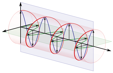
The electric field vectors of a traveling circularly polarized electromagnetic wave. This wave is right-circularly-polarized, since the direction of rotation of the vector is related by the right-hand rule to the direction the wave is moving; or left-circularly-polarized according to alternative convention.
In electrodynamics, circular polarization of an electromagnetic wave is a polarization state in which, at each point, the electromagnetic field of the wave has a constant magnitude and is rotating at a constant rate in a plane perpendicular to the direction of the wave.
In electrodynamics, the strength and direction of an electric field is defined by its electric field vector. In the case of a circularly polarized wave, as seen in the accompanying animation, the tip of the electric field vector, at a given point in space, relates to the phase of the light as it travels through time and space. At any instant of time, the electric field vector of the wave indicates a point on a helix oriented along the direction of propagation. A circularly polarized wave can rotate in one of two possible senses: clockwise or right-handed circular polarization (RHCP) in which the electric field vector rotates in a right-hand sense with respect to the direction of propagation, and counter-clockwise or left-handed circular polarization (LHCP) in which the vector rotates in a left-hand sense.
Circular polarization is a limiting case of elliptical polarization. The other special case is the easier-to-understand linear polarization. All three terms were coined by Augustin-Jean Fresnel, in a memoir read to the French Academy of Sciences on 9 December 1822.[1][2] Fresnel had first described the case of circular polarization, without yet naming it, in 1821.[3]
The phenomenon of polarization arises as a consequence of the fact that light behaves as a two-dimensional transverse wave.
Circular polarization occurs when the two orthogonal electric field component vectors are of equal magnitude and are out of phase by exactly 90°, or one-quarter wavelength.
General description[edit]


Right-handed/clockwise circularly polarized light displayed with and without the use of components. This would be considered left-handed/counterclockwise circularly polarized if defined from the point of view of the source rather than the receiver. Refer to the below convention section.[4]
On the right is an illustration of the electric field vectors of a circularly polarized electromagnetic wave.[4] The individual electric field vectors, as well as their combined vector, have a constant magnitude, and with changing phase angle. Given that this is a plane wave, each vector represents the magnitude and direction of the electric field for an entire plane that is perpendicular to the optical axis. Specifically, given that this is a circularly polarized plane wave, these vectors indicate that the electric field, from plane to plane, has a constant strength while its direction steadily rotates. Refer to these two images[dead link] in the plane wave article to better appreciate this dynamic. This light is considered to be right-hand, clockwise circularly polarized if viewed by the receiver. Since this is an electromagnetic wave, each electric field vector has a corresponding, but not illustrated, magnetic field vector that is at a right angle to the electric field vector and proportional in magnitude to it. As a result, the magnetic field vectors would trace out a second helix if displayed.
Circular polarization is often encountered in the field of optics and, in this section, the electromagnetic wave will be simply referred to as light.
The nature of circular polarization and its relationship to other polarizations is often understood by thinking of the electric field as being divided into two components that are perpendicular to each other. The vertical component and its corresponding plane are illustrated in blue, while the horizontal component and its corresponding plane are illustrated in green. Notice that the rightward (relative to the direction of travel) horizontal component leads the vertical component by one quarter of a wavelength, a 90° phase difference. It is this quadrature phase relationship that creates the helix and causes the points of maximum magnitude of the vertical component to correspond with the points of zero magnitude of the horizontal component, and vice versa. The result of this alignment are select vectors, corresponding to the helix, which exactly match the maxima of the vertical and horizontal components.
To appreciate how this quadrature phase shift corresponds to an electric field that rotates while maintaining a constant magnitude, imagine a dot traveling clockwise in a circle. Consider how the vertical and horizontal displacements of the dot, relative to the center of the circle, vary sinusoidally in time and are out of phase by one quarter of a cycle. The displacements are said to be out of phase by one quarter of a cycle because the horizontal maximum displacement (toward the left) is reached one quarter of a cycle before the vertical maximum displacement is reached. Now referring again to the illustration, imagine the center of the circle just described, traveling along the axis from the front to the back. The circling dot will trace out a helix with the displacement toward our viewing left, leading the vertical displacement. Just as the horizontal and vertical displacements of the rotating dot are out of phase by one quarter of a cycle in time, the magnitude of the horizontal and vertical components of the electric field are out of phase by one quarter of a wavelength.

Left-handed/counterclockwise circularly polarized light displayed with and without the use of components. This would be considered right-handed/clockwise circularly polarized if defined from the point of view of the source rather than the receiver.
The next pair of illustrations is that of left-handed, counterclockwise circularly polarized light when viewed by the receiver. Because it is left-handed, the rightward (relative to the direction of travel) horizontal component is now lagging the vertical component by one quarter of a wavelength, rather than leading it.
Reversal of handedness[edit]
Waveplate[edit]
To convert circularly polarized light to the other handedness, one can use a half-waveplate. A half-waveplate shifts a given linear component of light one half of a wavelength relative to its orthogonal linear component.
Reflection[edit]
The handedness of polarized light is reversed reflected off a surface at normal incidence. Upon such reflection, the rotation of the plane of polarization of the reflected light is identical to that of the incident field. However, with propagation now in the opposite direction, the same rotation direction that would be described as «right-handed» for the incident beam, is «left-handed» for propagation in the reverse direction, and vice versa. Aside from the reversal of handedness, the ellipticity of polarization is also preserved (except in cases of reflection by a birefringent surface).
Note that this principle only holds strictly for light reflected at normal incidence. For instance, right circularly polarized light reflected from a dielectric surface at grazing incidence (an angle beyond the Brewster angle) will still emerge as right-handed, but elliptically, polarized. Light reflected by a metal at non-normal incidence will generally have its ellipticity changed as well. Such situations may be solved by decomposing the incident circular (or other) polarization into components of linear polarization parallel and perpendicular to the plane of incidence, commonly denoted p and s respectively. The reflected components in the p and s linear polarizations are found by applying the Fresnel coefficients of reflection, which are generally different for those two linear polarizations. Only in the special case of normal incidence, where there is no distinction between p and s, are the Fresnel coefficients for the two components identical, leading to the above property.

A 3-slide series of pictures taken with and without a pair of MasterImage 3D circularly polarized movie glasses of some dead European rose chafers (Cetonia aurata) whose shiny green color comes from left-polarized light. Note that, without glasses, both the beetles and their images have shiny color. The right-polarizer removes the color of the beetles but leaves the color of the images. The left-polarizer does the opposite, showing reversal of handedness of the reflected light.
Conversion to and from linear polarization[edit]
Circularly polarized light can be converted into linearly polarized light by passing it through a quarter-waveplate. Passing linearly polarized light through a quarter-waveplate with its axes at 45° to its polarization axis will convert it to circular polarization. In fact, this is the most common way of producing circular polarization in practice. Note that passing linearly polarized light through a quarter-waveplate at an angle other than 45° will generally produce elliptical polarization.
Handedness conventions [edit]
A right-handed/clockwise circularly polarized wave as defined from the point of view of the source. It would be considered left-handed/anti-clockwise circularly polarized if defined from the point of view of the receiver.
A left-handed/anti-clockwise circularly polarized wave as defined from the point of view of the source. It would be considered right-handed/clockwise circularly polarized if defined from the point of view of the receiver.
Circular polarization may be referred to as right-handed or left-handed, and clockwise or anti-clockwise, depending on the direction in which the electric field vector rotates. Unfortunately, two opposing historical conventions exist.
From the point of view of the source[edit]
Using this convention, polarization is defined from the point of view of the source. When using this convention, left- or right-handedness is determined by pointing one’s left or right thumb away from the source, in the same direction that the wave is propagating, and matching the curling of one’s fingers to the direction of the temporal rotation of the field at a given point in space. When determining if the wave is clockwise or anti-clockwise circularly polarized, one again takes the point of view of the source, and while looking away from the source and in the same direction of the wave’s propagation, one observes the direction of the field’s spatial rotation.
Using this convention, the electric field vector of a left-handed circularly polarized wave is as follows:

As a specific example, refer to the circularly polarized wave in the first animation. Using this convention, that wave is defined as right-handed because when one points one’s right thumb in the same direction of the wave’s propagation, the fingers of that hand curl in the same direction of the field’s temporal rotation. It is considered clockwise circularly polarized because, from the point of view of the source, looking in the same direction of the wave’s propagation, the field rotates in the clockwise direction. The second animation is that of left-handed or anti-clockwise light, using this same convention.
This convention is in conformity with the Institute of Electrical and Electronics Engineers (IEEE) standard and, as a result, it is generally used in the engineering community.[5][6][7]
Quantum physicists also use this convention of handedness because it is consistent with their convention of handedness for a particle’s spin.[8]
Radio astronomers also use this convention in accordance with an International Astronomical Union (IAU) resolution made in 1973.[9]
From the point of view of the receiver[edit]
In this alternative convention, polarization is defined from the point of view of the receiver. Using this convention, left- or right-handedness is determined by pointing one’s left or right thumb toward the source, against the direction of propagation, and then matching the curling of one’s fingers to the spatial rotation of the field.
When using this convention, in contrast to the other convention, the defined handedness of the wave matches the handedness of the screw type nature of the field in space. Specifically, if one freezes a right-handed wave in time, when one curls the fingers of one’s right hand around the helix, the thumb will point in the direction of progression for the helix, given the sense of rotation. Note that, in the context of the nature of all screws and helices, it does not matter in which direction you point your thumb when determining its handedness.
When determining if the wave is clockwise or anti-clockwise circularly polarized, one again takes the point of view of the receiver and, while looking toward the source, against the direction of propagation, one observes the direction of the field’s temporal rotation.
Just as in the other convention, right-handedness corresponds to a clockwise rotation, and left-handedness corresponds to an anti-clockwise rotation.
Many optics textbooks use this second convention.[10][11] It is also used by SPIE[12] as well as the International Union of Pure and Applied Chemistry (IUPAC).[13]
Uses of the two conventions[edit]
As stated earlier, there is significant confusion with regards to these two conventions. As a general rule, the engineering, quantum physics, and radio astronomy communities use the first convention, in which the wave is observed from the point of view of the source.[6][8][9] In many physics textbooks dealing with optics, the second convention is used, in which the light is observed from the point of view of the receiver.[8][10]
To avoid confusion, it is good practice to specify «as defined from the point of view of the source» or «as defined from the point of view of the receiver» when discussing polarization matters.
The archive of the US Federal Standard 1037C proposes two contradictory conventions of handedness.[14]
FM radio[edit]
The term «circular polarization» is often used erroneously to describe mixed polarity signals[citation needed] used mostly in FM radio (87.5 to 108.0 MHz in the USA), in which a vertical and a horizontal component are propagated simultaneously by a single or a combined array. This has the effect of producing greater penetration into buildings and difficult reception areas than a signal with just one plane of polarization. This would be an instance in which the polarization would more appropriately be called random polarization because the polarization at a receiver, although constant, will vary depending on the direction from the transmitter and other factors in the transmitting antenna design. See Stokes parameters.
The term «FM radio» above refers to FM broadcasting, not two-way radio (more properly called land mobile radio), which uses vertical polarization almost exclusively.
Dichroism[edit]
Circular dichroism (CD) is the differential absorption of left- and right-handed circularly polarized light. Circular dichroism is the basis of a form of spectroscopy that can be used to determine the optical isomerism and secondary structure of molecules.
In general, this phenomenon will be exhibited in absorption bands of any optically active molecule. As a consequence, circular dichroism is exhibited by most biological molecules, because of the dextrorotary (e.g., some sugars) and levorotary (e.g., some amino acids) molecules they contain. Noteworthy as well is that a secondary structure will also impart a distinct CD to its respective molecules. Therefore, the alpha helix, beta sheet and random coil regions of proteins and the double helix of nucleic acids have CD spectral signatures representative of their structures.
Also, under the right conditions, even non-chiral molecules will exhibit magnetic circular dichroism — that is, circular dichroism induced by a magnetic field.
Luminescence[edit]
Circularly polarized luminescence (CPL) can occur when either a luminophore or an ensemble of luminophores is chiral. The extent to which emissions are polarized is quantified in the same way it is for circular dichroism, in terms of the dissymmetry factor, also sometimes referred to as the anisotropy factor. This value is given by:

where  corresponds to the quantum yield of left-handed circularly polarized light, and
  to that of right-handed light. The maximum absolute value of gem, corresponding to purely left- or right-handed circular polarization, is therefore 2. Meanwhile, the smallest absolute value that gem can achieve, corresponding to linearly polarized or unpolarized light, is zero.
Mathematical description[edit]
The classical sinusoidal plane wave solution of the electromagnetic wave equation for the electric and magnetic fields is:
![{displaystyle {begin{aligned}mathbf {E} (mathbf {r} ,t)&=left|,mathbf {E} ,right|mathrm {Re} left{mathbf {Q} left|psi rightrangle exp left[ileft(kz-omega tright)right]right}\mathbf {B} (mathbf {r} ,t)&={hat {mathbf {z} }}times mathbf {E} (mathbf {r} ,t)end{aligned}}}](https://wikimedia.org/api/rest_v1/media/math/render/svg/72e6f4e48ffd9eabf206d7664ee54e2e2ba2780c)
where k is the wavenumber;

is the angular frequency of the wave; ![mathbf{Q} = left [ hat{ mathbf{x}}, hat{mathbf{y}} right ]](https://wikimedia.org/api/rest_v1/media/math/render/svg/1c6f209c9644cf3ab69fd75e6d696bb9278c0c12) is an orthogonal
is an orthogonal  matrix whose columns span the transverse x-y plane; and
  is the speed of light.
Here,

is the amplitude of the field, and

is the normalized Jones vector in the x-y plane.
If  is rotated by
  radians with respect to
  and the x amplitude equals the y amplitude, the wave is circularly polarized. The Jones vector is:

where the plus sign indicates left circular polarization, and the minus sign indicates right circular polarization. In the case of circular polarization, the electric field vector of constant magnitude rotates in the x—y plane.
If basis vectors are defined such that:

and:

then the polarization state can be written in the «R-L basis» as:

where:

and:

Antennas[edit]
A number of different types of antenna elements can be used to produce circularly polarized (or nearly so) radiation; following Balanis,[15] one can use dipole elements:
«… two crossed dipoles provide the two orthogonal field components…. If the two dipoles are identical, the field intensity of each along zenith … would be of the same intensity. Also, if the two dipoles were fed with a 90° degree time-phase difference (phase quadrature), the polarization along zenith would be circular…. One way to obtain the 90° time-phase difference between the two orthogonal field components, radiated respectively by the two dipoles, is by feeding one of the two dipoles with a transmission line which is 1/4 wavelength longer or shorter than that of the other,» p.80;
or helical elements:
«To achieve circular polarization [in axial or end-fire mode] … the circumference C of the helix must be … with C/wavelength = 1 near optimum, and the spacing about S = wavelength/4,» p.571;
or patch elements:
«… circular and elliptical polarizations can be obtained using various feed arrangements or slight modifications made to the elements…. Circular polarization can be obtained if two orthogonal modes are excited with a 90° time-phase difference between them. This can be accomplished by adjusting the physical dimensions of the patch…. For a square patch element, the easiest way to excite ideally circular polarization is to feed the element at two adjacent edges…. The quadrature phase difference is obtained by feeding the element with a 90° power divider,» p.859.
In quantum mechanics[edit]
In the quantum mechanical view, light is composed of photons. Polarization is a manifestation of the spin angular momentum of light. More specifically, in quantum mechanics, the direction of spin of a photon is tied to the handedness of the circularly polarized light, and the spin of a beam of photons is similar to the spin of a beam of particles, such as electrons.[16]
In nature[edit]

The rose chafer’s external surface reflects almost exclusively left-circularly polarized light.
Only a few mechanisms in nature are known to systematically produce circularly polarized light. In 1911, Albert Abraham Michelson discovered that light reflected from the golden scarab beetle Chrysina resplendens is preferentially left-polarized. Since then, circular polarization has been measured in several other scarab beetles such as Chrysina gloriosa,[17] as well as some crustaceans such as the mantis shrimp. In these cases, the underlying mechanism is the molecular-level helicity of the chitinous cuticle.[18]
The bioluminescence of the larvae of fireflies is also circularly polarized, as reported in 1980 for the species Photuris lucicrescens and Photuris versicolor. For fireflies, it is more difficult to find a microscopic explanation for the polarization, because the left and right lanterns of the larvae were found to emit polarized light of opposite senses. The authors suggest that the light begins with a linear polarization due to inhomogeneities inside aligned photocytes, and it picks up circular polarization while passing through linearly birefringent tissue.[19]
Water-air interfaces provide another source of circular polarization. Sunlight that gets scattered back up towards the surface is linearly polarized. If this light is then totally internally reflected back down, its vertical component undergoes a phase shift. To an underwater observer looking up, the faint light outside Snell’s window therefore is (partially) circularly polarized.[20]
Weaker sources of circular polarization in nature include multiple scattering by linear polarizers[dubious – discuss], as in the circular polarization of starlight, and selective absorption by circularly dichroic media.
Radio emission from stars and pulsars can be strongly circularly polarized[citation needed].
Two species of mantis shrimp have been reported to be able to detect circular polarized light.[21][22]
See also[edit]
- Polarizer
- 3D film
- Chirality
- Sinusoidal plane-wave solutions of the electromagnetic wave equation
- Starlight polarization
- Waveplate
References[edit]
- ^ A. Fresnel, «Mémoire sur la double réfraction que les rayons lumineux éprouvent en traversant les aiguilles de cristal de roche suivant les directions parallèles à l’axe», read 9 December 1822; printed in H. de Senarmont, E. Verdet, and L. Fresnel (eds.), Oeuvres complètes d’Augustin Fresnel, vol. 1 (1866), pp. 731–51; translated as «Memoir on the double refraction that light rays undergo in traversing the needles of quartz in the directions parallel to the axis», Zenodo: 4745976, 2021 (open access); §§9–10.
- ^ Académie des Sciences, Procès-verbaux des séances de l’Académie tenues depuis la fondation de l’Institut jusqu’au mois d’août 1835, vol. 7 (for 1820–23), Hendaye, Basses Pyrénées: Imprimerie de l’Observatoire d’Abbadia, 1916, p. 401.
- ^ A. Fresnel, «Note sur le calcul des teintes que la polarisation développe dans les lames cristallisées» et seq., Annales de Chimie et de Physique, Ser. 2, vol. 17, pp. 102–11 (May 1821), 167–96 (June 1821), 312–15 («Postscript», July 1821); reprinted (with added section nos.) in H. de Senarmont, E. Verdet, and L. Fresnel (eds.), Oeuvres complètes d’Augustin Fresnel, vol. 1 (1866), pp. 609–48; translated as «On the calculation of the tints that polarization develops in crystalline plates, & postscript», Zenodo: 4058004 (Creative Commons), 2021; author’s footnote to §16.
- ^ a b For handedness conventions, refer to the well-referenced section Left/Right Handedness Conventions
- ^ IEEE Std 149-1979 (R2008), «IEEE Standard Test Procedures for Antennas». Reaffirmed December 10, 2008, Approved December 15, 1977, IEEE-SA Standards Board. Approved October 9, 2003, American National Standards Institute. ISBN 0-471-08032-2. doi:10.1109/IEEESTD.1979.120310, sec. 11.1, p. 61.»the sense of polarization, or handedness … is called right handed (left handed) if the direction of rotation is clockwise (anti-clockwise) for an observer looking in the direction of propagation»
- ^ a b Electromagnetic Waves & Antennas – S. J. Orfanidis: Footnote p.45, «most engineering texts use the IEEE convention and most physics texts, the opposite convention.»
- ^ Electromagnetic Waves & Antennas – S. J. Orfanidis Pg 44 «Curl the fingers of your left and right hands into a fist and point both thumbs towards the direction of propagation»
- ^ a b c Lectures on Physics Feynman (Vol. 1, ch.33-1) «If the end of the electric vector, when we look at it as the light comes straight toward us, goes around in an anti-clockwise direction, we call it right-hand circular polarization. … Our convention for labeling left-hand and right-hand circular polarization is consistent with that which is used today for all the other particles in physics which exhibit polarization (e.g., electrons). However, in some books on optics the opposite conventions are used, so one must be careful.»
- ^ a b IAU General Assembly Meeting, 1973, Commission 40 (Radio Astronomy/Radioastronomie), 8. POLARIZATION DEFINITIONS — «A working Group chaired by Westerhout was convened to discuss the definition of polarization brightness temperatures used in the description of polarized extended objects and the galactic
background. The following resolution was adopted by Commissions 25 and 40: ‘RESOLVED, that the frame of reference for the Stokes parameters is that of Right Ascension and Declination with the position angle of electric-vector maximum, q, starting from North and increasing through East. Elliptical polarization is defined in conformity with the definitions of the Institute of Electrical and Electronics Engineers (IEEE Standard 211, 1969). This means that the polarization of incoming radiation, for which the position angle, q, of the electric vector, measured at a fixed point in space, increases with time, is described as right-handed and positive.'» - ^ a b Polarization in Spectral Lines. 2004 E. Landi Degl’innocenti, M Landolfi Section 1.2 «When … the tip of the electric field vector rotates clockwise for an observer facing the radiation source, … (it will be considered)… positive (or righthanded) circular polarization, Our convention … agrees with those proposed in the classical textbooks on polarized light by Shurcliff (1952) and by Clarke and Grainger (1971). The same convention is also used, although with some few exceptions, by optical astronomers working in the field of polarimetry. Many radio astronomers, on the other hand, use the opposite convention. [1]
- ^ HANDBOOK OPTICS Volume I,Devices, Measurements and Properties,Michael Bass Page 272 Footnote: «Right-circularly polarized light is defined as a clockwise rotation of the electric vector when the observer is looking against the direction the wave is traveling.»
- ^ «The Polarization Ellipse». spie.org. Retrieved 13 April 2018.
- ^ S. E. Braslavsky (1 January 2009). «Glossary of terms used in photochemistry, 3rd edition (IUPAC Recommendations 2006)» (PDF). Pure and Applied Chemistry. 79 (3): 293–465. doi:10.1351/pac200779030293. S2CID 96601716. Archived (PDF) from the original on 2022-10-09.
- ^ In one location it is stated…»Note 1. … In general, the figure, i.e., polarization, is elliptical and is traced in a clockwise or anti-clockwise sense, as viewed in the direction of propagation. … Rotation of the electric vector in a clockwise sense is designated right-hand polarization, and rotation in an anti-clockwise sense is designated left-hand polarization. «[2] Archived 2011-05-14 at the Wayback Machine In another location it is stated… «Note 4: Circular polarization may be referred to as «right-hand» or «left-hand», depending on whether the helix describes the thread of a right-hand or left-hand screw, respectively». [3] Archived 2011-06-06 at the Wayback Machine
- ^ Balanis, Constantine A. «Antenna Theory – Analysis and Design», 2005, 3rd Edition, John Wiley & Sons.
- ^ Introduction to Quantum Theory 2ED David Park Sec 2.2 Pg32 «… the polarization of a beam of light is exactly the same kind of thing as the spin of a beam of electrons, the differences of terminology reflecting only the accidents of the historical order of discovery.»
- ^ Srinivasarao, Mohan; Park, Jung Ok; Crne, Matija; Sharma, Vivek (July 24, 2009). «Structural Origin of Circularly Polarized Iridescence in Jeweled Beetles». Science. 325 (5939): 449–451. Bibcode:2009Sci…325..449S. doi:10.1126/science.1172051. PMID 19628862. S2CID 206519071 – via science.sciencemag.org.
- ^ Hegedüs, Ramón; Győző Szélb; Gábor Horváth (September 2006). «Imaging polarimetry of the circularly polarizing cuticle of scarab beetles (Coleoptera: Rutelidae, Cetoniidae)». Vision Research. 46 (17): 2786–2797. doi:10.1016/j.visres.2006.02.007. PMID 16564066. S2CID 14974820.
- ^ Wynberg, Hans; Meijer, E.W.; Hummelen, J.C.; Dekkers, H.P.J.M.; Schippers, P.H.; Carlson, A.D. (7 August 1980). «Circular polarization observed in bioluminescence» (PDF). Nature. 286 (5773): 641–642. Bibcode:1980Natur.286..641W. doi:10.1038/286641a0. S2CID 4324467. Archived from the original (PDF) on 24 July 2011.
- ^ Horváth, Gábor; Dezsö Varjú (2003). Polarized Light in Animal Vision: Polarization Patterns in Nature. Springer. pp. 100–103. ISBN 978-3-540-40457-6.
- ^ Tsyr-Huei Chiou; Sonja Kleinlogel; Tom Cronin; Roy Caldwell; Birte Loeffler; Afsheen Siddiqi; Alan Goldizen; Justin Marshall (2008). «Circular polarization vision in a stomatopod crustacean». Current Biology. 18 (6): 429–34. doi:10.1016/j.cub.2008.02.066. PMID 18356053. S2CID 6925705.
- ^ Sonja Kleinlogel; Andrew White (2008). «The secret world of shrimps: polarisation vision at its best». PLoS ONE. 3 (5): e2190. arXiv:0804.2162. Bibcode:2008PLoSO…3.2190K. doi:10.1371/journal.pone.0002190. PMC 2377063. PMID 18478095.
External links[edit]
- Circularly polarized light: beetles and displays
- Article on the mantis shrimp and circular polarization
- Animation of Circular Polarization (on YouTube)
- Comparison of Circular Polarization with Linear and Elliptical Polarizations (YouTube Animation)
- Reversal of handedness of circularly polarized light by mirror. A demonstration – simple, cheap & instructive
Further reading[edit]
- Jackson, John D. (1999). Classical Electrodynamics (3rd ed.). New York: Wiley. ISBN 978-0-471-30932-1.
- Born, M. & Wolf, E. (1999). Principles of Optics: Electromagnetic Theory of Propagation, Interference and Diffraction of Light (7th ed.). Cambridge: Cambridge University Press. ISBN 978-0-521-64222-4.
The electric field vectors of a traveling circularly polarized electromagnetic wave. This wave is right-circularly-polarized, since the direction of rotation of the vector is related by the right-hand rule to the direction the wave is moving; or left-circularly-polarized according to alternative convention.
In electrodynamics, circular polarization of an electromagnetic wave is a polarization state in which, at each point, the electromagnetic field of the wave has a constant magnitude and is rotating at a constant rate in a plane perpendicular to the direction of the wave.
In electrodynamics, the strength and direction of an electric field is defined by its electric field vector. In the case of a circularly polarized wave, as seen in the accompanying animation, the tip of the electric field vector, at a given point in space, relates to the phase of the light as it travels through time and space. At any instant of time, the electric field vector of the wave indicates a point on a helix oriented along the direction of propagation. A circularly polarized wave can rotate in one of two possible senses: clockwise or right-handed circular polarization (RHCP) in which the electric field vector rotates in a right-hand sense with respect to the direction of propagation, and counter-clockwise or left-handed circular polarization (LHCP) in which the vector rotates in a left-hand sense.
Circular polarization is a limiting case of elliptical polarization. The other special case is the easier-to-understand linear polarization. All three terms were coined by Augustin-Jean Fresnel, in a memoir read to the French Academy of Sciences on 9 December 1822.[1][2] Fresnel had first described the case of circular polarization, without yet naming it, in 1821.[3]
The phenomenon of polarization arises as a consequence of the fact that light behaves as a two-dimensional transverse wave.
Circular polarization occurs when the two orthogonal electric field component vectors are of equal magnitude and are out of phase by exactly 90°, or one-quarter wavelength.
General description[edit]
Right-handed/clockwise circularly polarized light displayed with and without the use of components. This would be considered left-handed/counterclockwise circularly polarized if defined from the point of view of the source rather than the receiver. Refer to the below convention section.[4]
On the right is an illustration of the electric field vectors of a circularly polarized electromagnetic wave.[4] The individual electric field vectors, as well as their combined vector, have a constant magnitude, and with changing phase angle. Given that this is a plane wave, each vector represents the magnitude and direction of the electric field for an entire plane that is perpendicular to the optical axis. Specifically, given that this is a circularly polarized plane wave, these vectors indicate that the electric field, from plane to plane, has a constant strength while its direction steadily rotates. Refer to these two images[dead link] in the plane wave article to better appreciate this dynamic. This light is considered to be right-hand, clockwise circularly polarized if viewed by the receiver. Since this is an electromagnetic wave, each electric field vector has a corresponding, but not illustrated, magnetic field vector that is at a right angle to the electric field vector and proportional in magnitude to it. As a result, the magnetic field vectors would trace out a second helix if displayed.
Circular polarization is often encountered in the field of optics and, in this section, the electromagnetic wave will be simply referred to as light.
The nature of circular polarization and its relationship to other polarizations is often understood by thinking of the electric field as being divided into two components that are perpendicular to each other. The vertical component and its corresponding plane are illustrated in blue, while the horizontal component and its corresponding plane are illustrated in green. Notice that the rightward (relative to the direction of travel) horizontal component leads the vertical component by one quarter of a wavelength, a 90° phase difference. It is this quadrature phase relationship that creates the helix and causes the points of maximum magnitude of the vertical component to correspond with the points of zero magnitude of the horizontal component, and vice versa. The result of this alignment are select vectors, corresponding to the helix, which exactly match the maxima of the vertical and horizontal components.
To appreciate how this quadrature phase shift corresponds to an electric field that rotates while maintaining a constant magnitude, imagine a dot traveling clockwise in a circle. Consider how the vertical and horizontal displacements of the dot, relative to the center of the circle, vary sinusoidally in time and are out of phase by one quarter of a cycle. The displacements are said to be out of phase by one quarter of a cycle because the horizontal maximum displacement (toward the left) is reached one quarter of a cycle before the vertical maximum displacement is reached. Now referring again to the illustration, imagine the center of the circle just described, traveling along the axis from the front to the back. The circling dot will trace out a helix with the displacement toward our viewing left, leading the vertical displacement. Just as the horizontal and vertical displacements of the rotating dot are out of phase by one quarter of a cycle in time, the magnitude of the horizontal and vertical components of the electric field are out of phase by one quarter of a wavelength.
Left-handed/counterclockwise circularly polarized light displayed with and without the use of components. This would be considered right-handed/clockwise circularly polarized if defined from the point of view of the source rather than the receiver.
The next pair of illustrations is that of left-handed, counterclockwise circularly polarized light when viewed by the receiver. Because it is left-handed, the rightward (relative to the direction of travel) horizontal component is now lagging the vertical component by one quarter of a wavelength, rather than leading it.
Reversal of handedness[edit]
Waveplate[edit]
To convert circularly polarized light to the other handedness, one can use a half-waveplate. A half-waveplate shifts a given linear component of light one half of a wavelength relative to its orthogonal linear component.
Reflection[edit]
The handedness of polarized light is reversed reflected off a surface at normal incidence. Upon such reflection, the rotation of the plane of polarization of the reflected light is identical to that of the incident field. However, with propagation now in the opposite direction, the same rotation direction that would be described as «right-handed» for the incident beam, is «left-handed» for propagation in the reverse direction, and vice versa. Aside from the reversal of handedness, the ellipticity of polarization is also preserved (except in cases of reflection by a birefringent surface).
Note that this principle only holds strictly for light reflected at normal incidence. For instance, right circularly polarized light reflected from a dielectric surface at grazing incidence (an angle beyond the Brewster angle) will still emerge as right-handed, but elliptically, polarized. Light reflected by a metal at non-normal incidence will generally have its ellipticity changed as well. Such situations may be solved by decomposing the incident circular (or other) polarization into components of linear polarization parallel and perpendicular to the plane of incidence, commonly denoted p and s respectively. The reflected components in the p and s linear polarizations are found by applying the Fresnel coefficients of reflection, which are generally different for those two linear polarizations. Only in the special case of normal incidence, where there is no distinction between p and s, are the Fresnel coefficients for the two components identical, leading to the above property.
A 3-slide series of pictures taken with and without a pair of MasterImage 3D circularly polarized movie glasses of some dead European rose chafers (Cetonia aurata) whose shiny green color comes from left-polarized light. Note that, without glasses, both the beetles and their images have shiny color. The right-polarizer removes the color of the beetles but leaves the color of the images. The left-polarizer does the opposite, showing reversal of handedness of the reflected light.
Conversion to and from linear polarization[edit]
Circularly polarized light can be converted into linearly polarized light by passing it through a quarter-waveplate. Passing linearly polarized light through a quarter-waveplate with its axes at 45° to its polarization axis will convert it to circular polarization. In fact, this is the most common way of producing circular polarization in practice. Note that passing linearly polarized light through a quarter-waveplate at an angle other than 45° will generally produce elliptical polarization.
Handedness conventions [edit]
A right-handed/clockwise circularly polarized wave as defined from the point of view of the source. It would be considered left-handed/anti-clockwise circularly polarized if defined from the point of view of the receiver.
A left-handed/anti-clockwise circularly polarized wave as defined from the point of view of the source. It would be considered right-handed/clockwise circularly polarized if defined from the point of view of the receiver.
Circular polarization may be referred to as right-handed or left-handed, and clockwise or anti-clockwise, depending on the direction in which the electric field vector rotates. Unfortunately, two opposing historical conventions exist.
From the point of view of the source[edit]
Using this convention, polarization is defined from the point of view of the source. When using this convention, left- or right-handedness is determined by pointing one’s left or right thumb away from the source, in the same direction that the wave is propagating, and matching the curling of one’s fingers to the direction of the temporal rotation of the field at a given point in space. When determining if the wave is clockwise or anti-clockwise circularly polarized, one again takes the point of view of the source, and while looking away from the source and in the same direction of the wave’s propagation, one observes the direction of the field’s spatial rotation.
Using this convention, the electric field vector of a left-handed circularly polarized wave is as follows:
As a specific example, refer to the circularly polarized wave in the first animation. Using this convention, that wave is defined as right-handed because when one points one’s right thumb in the same direction of the wave’s propagation, the fingers of that hand curl in the same direction of the field’s temporal rotation. It is considered clockwise circularly polarized because, from the point of view of the source, looking in the same direction of the wave’s propagation, the field rotates in the clockwise direction. The second animation is that of left-handed or anti-clockwise light, using this same convention.
This convention is in conformity with the Institute of Electrical and Electronics Engineers (IEEE) standard and, as a result, it is generally used in the engineering community.[5][6][7]
Quantum physicists also use this convention of handedness because it is consistent with their convention of handedness for a particle’s spin.[8]
Radio astronomers also use this convention in accordance with an International Astronomical Union (IAU) resolution made in 1973.[9]
From the point of view of the receiver[edit]
In this alternative convention, polarization is defined from the point of view of the receiver. Using this convention, left- or right-handedness is determined by pointing one’s left or right thumb toward the source, against the direction of propagation, and then matching the curling of one’s fingers to the spatial rotation of the field.
When using this convention, in contrast to the other convention, the defined handedness of the wave matches the handedness of the screw type nature of the field in space. Specifically, if one freezes a right-handed wave in time, when one curls the fingers of one’s right hand around the helix, the thumb will point in the direction of progression for the helix, given the sense of rotation. Note that, in the context of the nature of all screws and helices, it does not matter in which direction you point your thumb when determining its handedness.
When determining if the wave is clockwise or anti-clockwise circularly polarized, one again takes the point of view of the receiver and, while looking toward the source, against the direction of propagation, one observes the direction of the field’s temporal rotation.
Just as in the other convention, right-handedness corresponds to a clockwise rotation, and left-handedness corresponds to an anti-clockwise rotation.
Many optics textbooks use this second convention.[10][11] It is also used by SPIE[12] as well as the International Union of Pure and Applied Chemistry (IUPAC).[13]
Uses of the two conventions[edit]
As stated earlier, there is significant confusion with regards to these two conventions. As a general rule, the engineering, quantum physics, and radio astronomy communities use the first convention, in which the wave is observed from the point of view of the source.[6][8][9] In many physics textbooks dealing with optics, the second convention is used, in which the light is observed from the point of view of the receiver.[8][10]
To avoid confusion, it is good practice to specify «as defined from the point of view of the source» or «as defined from the point of view of the receiver» when discussing polarization matters.
The archive of the US Federal Standard 1037C proposes two contradictory conventions of handedness.[14]
FM radio[edit]
The term «circular polarization» is often used erroneously to describe mixed polarity signals[citation needed] used mostly in FM radio (87.5 to 108.0 MHz in the USA), in which a vertical and a horizontal component are propagated simultaneously by a single or a combined array. This has the effect of producing greater penetration into buildings and difficult reception areas than a signal with just one plane of polarization. This would be an instance in which the polarization would more appropriately be called random polarization because the polarization at a receiver, although constant, will vary depending on the direction from the transmitter and other factors in the transmitting antenna design. See Stokes parameters.
The term «FM radio» above refers to FM broadcasting, not two-way radio (more properly called land mobile radio), which uses vertical polarization almost exclusively.
Dichroism[edit]
Circular dichroism (CD) is the differential absorption of left- and right-handed circularly polarized light. Circular dichroism is the basis of a form of spectroscopy that can be used to determine the optical isomerism and secondary structure of molecules.
In general, this phenomenon will be exhibited in absorption bands of any optically active molecule. As a consequence, circular dichroism is exhibited by most biological molecules, because of the dextrorotary (e.g., some sugars) and levorotary (e.g., some amino acids) molecules they contain. Noteworthy as well is that a secondary structure will also impart a distinct CD to its respective molecules. Therefore, the alpha helix, beta sheet and random coil regions of proteins and the double helix of nucleic acids have CD spectral signatures representative of their structures.
Also, under the right conditions, even non-chiral molecules will exhibit magnetic circular dichroism — that is, circular dichroism induced by a magnetic field.
Luminescence[edit]
Circularly polarized luminescence (CPL) can occur when either a luminophore or an ensemble of luminophores is chiral. The extent to which emissions are polarized is quantified in the same way it is for circular dichroism, in terms of the dissymmetry factor, also sometimes referred to as the anisotropy factor. This value is given by:
where corresponds to the quantum yield of left-handed circularly polarized light, and to that of right-handed light. The maximum absolute value of gem, corresponding to purely left- or right-handed circular polarization, is therefore 2. Meanwhile, the smallest absolute value that gem can achieve, corresponding to linearly polarized or unpolarized light, is zero.
Mathematical description[edit]
The classical sinusoidal plane wave solution of the electromagnetic wave equation for the electric and magnetic fields is:
where k is the wavenumber;
is the angular frequency of the wave; is an orthogonal matrix whose columns span the transverse x-y plane; and is the speed of light.
Here,
is the amplitude of the field, and
is the normalized Jones vector in the x-y plane.
If is rotated by radians with respect to and the x amplitude equals the y amplitude, the wave is circularly polarized. The Jones vector is:
where the plus sign indicates left circular polarization, and the minus sign indicates right circular polarization. In the case of circular polarization, the electric field vector of constant magnitude rotates in the x—y plane.
If basis vectors are defined such that:
and:
then the polarization state can be written in the «R-L basis» as:
where:
and:
Antennas[edit]
A number of different types of antenna elements can be used to produce circularly polarized (or nearly so) radiation; following Balanis,[15] one can use dipole elements:
«… two crossed dipoles provide the two orthogonal field components…. If the two dipoles are identical, the field intensity of each along zenith … would be of the same intensity. Also, if the two dipoles were fed with a 90° degree time-phase difference (phase quadrature), the polarization along zenith would be circular…. One way to obtain the 90° time-phase difference between the two orthogonal field components, radiated respectively by the two dipoles, is by feeding one of the two dipoles with a transmission line which is 1/4 wavelength longer or shorter than that of the other,» p.80;
or helical elements:
«To achieve circular polarization [in axial or end-fire mode] … the circumference C of the helix must be … with C/wavelength = 1 near optimum, and the spacing about S = wavelength/4,» p.571;
or patch elements:
«… circular and elliptical polarizations can be obtained using various feed arrangements or slight modifications made to the elements…. Circular polarization can be obtained if two orthogonal modes are excited with a 90° time-phase difference between them. This can be accomplished by adjusting the physical dimensions of the patch…. For a square patch element, the easiest way to excite ideally circular polarization is to feed the element at two adjacent edges…. The quadrature phase difference is obtained by feeding the element with a 90° power divider,» p.859.
In quantum mechanics[edit]
In the quantum mechanical view, light is composed of photons. Polarization is a manifestation of the spin angular momentum of light. More specifically, in quantum mechanics, the direction of spin of a photon is tied to the handedness of the circularly polarized light, and the spin of a beam of photons is similar to the spin of a beam of particles, such as electrons.[16]
In nature[edit]
The rose chafer’s external surface reflects almost exclusively left-circularly polarized light.
Only a few mechanisms in nature are known to systematically produce circularly polarized light. In 1911, Albert Abraham Michelson discovered that light reflected from the golden scarab beetle Chrysina resplendens is preferentially left-polarized. Since then, circular polarization has been measured in several other scarab beetles such as Chrysina gloriosa,[17] as well as some crustaceans such as the mantis shrimp. In these cases, the underlying mechanism is the molecular-level helicity of the chitinous cuticle.[18]
The bioluminescence of the larvae of fireflies is also circularly polarized, as reported in 1980 for the species Photuris lucicrescens and Photuris versicolor. For fireflies, it is more difficult to find a microscopic explanation for the polarization, because the left and right lanterns of the larvae were found to emit polarized light of opposite senses. The authors suggest that the light begins with a linear polarization due to inhomogeneities inside aligned photocytes, and it picks up circular polarization while passing through linearly birefringent tissue.[19]
Water-air interfaces provide another source of circular polarization. Sunlight that gets scattered back up towards the surface is linearly polarized. If this light is then totally internally reflected back down, its vertical component undergoes a phase shift. To an underwater observer looking up, the faint light outside Snell’s window therefore is (partially) circularly polarized.[20]
Weaker sources of circular polarization in nature include multiple scattering by linear polarizers[dubious – discuss], as in the circular polarization of starlight, and selective absorption by circularly dichroic media.
Radio emission from stars and pulsars can be strongly circularly polarized[citation needed].
Two species of mantis shrimp have been reported to be able to detect circular polarized light.[21][22]
See also[edit]
- Polarizer
- 3D film
- Chirality
- Sinusoidal plane-wave solutions of the electromagnetic wave equation
- Starlight polarization
- Waveplate
References[edit]
- ^ A. Fresnel, «Mémoire sur la double réfraction que les rayons lumineux éprouvent en traversant les aiguilles de cristal de roche suivant les directions parallèles à l’axe», read 9 December 1822; printed in H. de Senarmont, E. Verdet, and L. Fresnel (eds.), Oeuvres complètes d’Augustin Fresnel, vol. 1 (1866), pp. 731–51; translated as «Memoir on the double refraction that light rays undergo in traversing the needles of quartz in the directions parallel to the axis», Zenodo: 4745976, 2021 (open access); §§9–10.
- ^ Académie des Sciences, Procès-verbaux des séances de l’Académie tenues depuis la fondation de l’Institut jusqu’au mois d’août 1835, vol. 7 (for 1820–23), Hendaye, Basses Pyrénées: Imprimerie de l’Observatoire d’Abbadia, 1916, p. 401.
- ^ A. Fresnel, «Note sur le calcul des teintes que la polarisation développe dans les lames cristallisées» et seq., Annales de Chimie et de Physique, Ser. 2, vol. 17, pp. 102–11 (May 1821), 167–96 (June 1821), 312–15 («Postscript», July 1821); reprinted (with added section nos.) in H. de Senarmont, E. Verdet, and L. Fresnel (eds.), Oeuvres complètes d’Augustin Fresnel, vol. 1 (1866), pp. 609–48; translated as «On the calculation of the tints that polarization develops in crystalline plates, & postscript», Zenodo: 4058004 (Creative Commons), 2021; author’s footnote to §16.
- ^ a b For handedness conventions, refer to the well-referenced section Left/Right Handedness Conventions
- ^ IEEE Std 149-1979 (R2008), «IEEE Standard Test Procedures for Antennas». Reaffirmed December 10, 2008, Approved December 15, 1977, IEEE-SA Standards Board. Approved October 9, 2003, American National Standards Institute. ISBN 0-471-08032-2. doi:10.1109/IEEESTD.1979.120310, sec. 11.1, p. 61.»the sense of polarization, or handedness … is called right handed (left handed) if the direction of rotation is clockwise (anti-clockwise) for an observer looking in the direction of propagation»
- ^ a b Electromagnetic Waves & Antennas – S. J. Orfanidis: Footnote p.45, «most engineering texts use the IEEE convention and most physics texts, the opposite convention.»
- ^ Electromagnetic Waves & Antennas – S. J. Orfanidis Pg 44 «Curl the fingers of your left and right hands into a fist and point both thumbs towards the direction of propagation»
- ^ a b c Lectures on Physics Feynman (Vol. 1, ch.33-1) «If the end of the electric vector, when we look at it as the light comes straight toward us, goes around in an anti-clockwise direction, we call it right-hand circular polarization. … Our convention for labeling left-hand and right-hand circular polarization is consistent with that which is used today for all the other particles in physics which exhibit polarization (e.g., electrons). However, in some books on optics the opposite conventions are used, so one must be careful.»
- ^ a b IAU General Assembly Meeting, 1973, Commission 40 (Radio Astronomy/Radioastronomie), 8. POLARIZATION DEFINITIONS — «A working Group chaired by Westerhout was convened to discuss the definition of polarization brightness temperatures used in the description of polarized extended objects and the galactic
background. The following resolution was adopted by Commissions 25 and 40: ‘RESOLVED, that the frame of reference for the Stokes parameters is that of Right Ascension and Declination with the position angle of electric-vector maximum, q, starting from North and increasing through East. Elliptical polarization is defined in conformity with the definitions of the Institute of Electrical and Electronics Engineers (IEEE Standard 211, 1969). This means that the polarization of incoming radiation, for which the position angle, q, of the electric vector, measured at a fixed point in space, increases with time, is described as right-handed and positive.'» - ^ a b Polarization in Spectral Lines. 2004 E. Landi Degl’innocenti, M Landolfi Section 1.2 «When … the tip of the electric field vector rotates clockwise for an observer facing the radiation source, … (it will be considered)… positive (or righthanded) circular polarization, Our convention … agrees with those proposed in the classical textbooks on polarized light by Shurcliff (1952) and by Clarke and Grainger (1971). The same convention is also used, although with some few exceptions, by optical astronomers working in the field of polarimetry. Many radio astronomers, on the other hand, use the opposite convention. [1]
- ^ HANDBOOK OPTICS Volume I,Devices, Measurements and Properties,Michael Bass Page 272 Footnote: «Right-circularly polarized light is defined as a clockwise rotation of the electric vector when the observer is looking against the direction the wave is traveling.»
- ^ «The Polarization Ellipse». spie.org. Retrieved 13 April 2018.
- ^ S. E. Braslavsky (1 January 2009). «Glossary of terms used in photochemistry, 3rd edition (IUPAC Recommendations 2006)» (PDF). Pure and Applied Chemistry. 79 (3): 293–465. doi:10.1351/pac200779030293. S2CID 96601716. Archived (PDF) from the original on 2022-10-09.
- ^ In one location it is stated…»Note 1. … In general, the figure, i.e., polarization, is elliptical and is traced in a clockwise or anti-clockwise sense, as viewed in the direction of propagation. … Rotation of the electric vector in a clockwise sense is designated right-hand polarization, and rotation in an anti-clockwise sense is designated left-hand polarization. «[2] Archived 2011-05-14 at the Wayback Machine In another location it is stated… «Note 4: Circular polarization may be referred to as «right-hand» or «left-hand», depending on whether the helix describes the thread of a right-hand or left-hand screw, respectively». [3] Archived 2011-06-06 at the Wayback Machine
- ^ Balanis, Constantine A. «Antenna Theory – Analysis and Design», 2005, 3rd Edition, John Wiley & Sons.
- ^ Introduction to Quantum Theory 2ED David Park Sec 2.2 Pg32 «… the polarization of a beam of light is exactly the same kind of thing as the spin of a beam of electrons, the differences of terminology reflecting only the accidents of the historical order of discovery.»
- ^ Srinivasarao, Mohan; Park, Jung Ok; Crne, Matija; Sharma, Vivek (July 24, 2009). «Structural Origin of Circularly Polarized Iridescence in Jeweled Beetles». Science. 325 (5939): 449–451. Bibcode:2009Sci…325..449S. doi:10.1126/science.1172051. PMID 19628862. S2CID 206519071 – via science.sciencemag.org.
- ^ Hegedüs, Ramón; Győző Szélb; Gábor Horváth (September 2006). «Imaging polarimetry of the circularly polarizing cuticle of scarab beetles (Coleoptera: Rutelidae, Cetoniidae)». Vision Research. 46 (17): 2786–2797. doi:10.1016/j.visres.2006.02.007. PMID 16564066. S2CID 14974820.
- ^ Wynberg, Hans; Meijer, E.W.; Hummelen, J.C.; Dekkers, H.P.J.M.; Schippers, P.H.; Carlson, A.D. (7 August 1980). «Circular polarization observed in bioluminescence» (PDF). Nature. 286 (5773): 641–642. Bibcode:1980Natur.286..641W. doi:10.1038/286641a0. S2CID 4324467. Archived from the original (PDF) on 24 July 2011.
- ^ Horváth, Gábor; Dezsö Varjú (2003). Polarized Light in Animal Vision: Polarization Patterns in Nature. Springer. pp. 100–103. ISBN 978-3-540-40457-6.
- ^ Tsyr-Huei Chiou; Sonja Kleinlogel; Tom Cronin; Roy Caldwell; Birte Loeffler; Afsheen Siddiqi; Alan Goldizen; Justin Marshall (2008). «Circular polarization vision in a stomatopod crustacean». Current Biology. 18 (6): 429–34. doi:10.1016/j.cub.2008.02.066. PMID 18356053. S2CID 6925705.
- ^ Sonja Kleinlogel; Andrew White (2008). «The secret world of shrimps: polarisation vision at its best». PLoS ONE. 3 (5): e2190. arXiv:0804.2162. Bibcode:2008PLoSO…3.2190K. doi:10.1371/journal.pone.0002190. PMC 2377063. PMID 18478095.
External links[edit]
- Circularly polarized light: beetles and displays
- Article on the mantis shrimp and circular polarization
- Animation of Circular Polarization (on YouTube)
- Comparison of Circular Polarization with Linear and Elliptical Polarizations (YouTube Animation)
- Reversal of handedness of circularly polarized light by mirror. A demonstration – simple, cheap & instructive
Further reading[edit]
- Jackson, John D. (1999). Classical Electrodynamics (3rd ed.). New York: Wiley. ISBN 978-0-471-30932-1.
- Born, M. & Wolf, E. (1999). Principles of Optics: Electromagnetic Theory of Propagation, Interference and Diffraction of Light (7th ed.). Cambridge: Cambridge University Press. ISBN 978-0-521-64222-4.
Photon polarization is the quantum mechanical description of the classical polarized sinusoidal plane electromagnetic wave. An individual photon
can be described as having right or left circular polarization, or a superposition of the two. Equivalently, a photon can be described as having horizontal or vertical linear polarization, or a superposition of the two.
The description of photon polarization contains many of the physical concepts and much of the mathematical machinery of more involved quantum descriptions, such as the quantum mechanics of an electron in a potential well. Polarization is an example of a qubit degree of freedom, which forms a fundamental basis for an understanding of more complicated quantum phenomena. Much of the mathematical machinery of quantum mechanics, such as state vectors, probability amplitudes, unitary operators, and Hermitian operators, emerge naturally from the classical Maxwell’s equations in the description. The quantum polarization state vector for the photon, for instance, is identical with the Jones vector, usually used to describe the polarization of a classical wave. Unitary operators emerge from the classical requirement of the conservation of energy of a classical wave propagating through lossless media that alter the polarization state of the wave. Hermitian operators then follow for infinitesimal transformations of a classical polarization state.
Many of the implications of the mathematical machinery are easily verified experimentally. In fact, many of the experiments can be performed with polaroid sunglass lenses.
The connection with quantum mechanics is made through the identification of a minimum packet size, called a photon, for energy in the electromagnetic field. The identification is based on the theories of Planck and the interpretation of those theories by Einstein. The correspondence principle then allows the identification of momentum and angular momentum (called spin), as well as energy, with the photon.
Polarization of classical electromagnetic waves[edit]
Polarization states[edit]
Linear polarization[edit]

Effect of a polarizer on reflection from mud flats. In the first picture, the polarizer is rotated to minimize the effect; in the second it is rotated 90° to maximize it: almost all reflected sunlight is eliminated.
The wave is linearly polarized (or plane polarized) when the phase angles
 are equal,

This represents a wave with phase  polarized at an angle
  with respect to the x axis.
In this case the Jones vector

can be written with a single phase:

The state vectors for linear polarization in x or y are special cases of this state vector.
If unit vectors are defined such that

and

then the linearly polarized polarization state can be written in the «x-y basis» as

Circular polarization[edit]
If the phase angles and differ by exactly and the x amplitude equals the y amplitude the wave is circularly polarized. The Jones vector then becomes

where the plus sign indicates left circular polarization and the minus sign indicates right circular polarization. In the case of circular polarization, the electric field vector of constant magnitude rotates in the x-y plane.
If unit vectors are defined such that

and

then an arbitrary polarization state can be written in the «R-L basis» as

where

and

We can see that

Elliptical polarization[edit]
The general case in which the electric field rotates in the x-y plane and has variable magnitude is called elliptical polarization. The state vector is given by

Geometric visualization of an arbitrary polarization state[edit]
To get an understanding of what a polarization state looks like, one can observe the orbit that is made if the polarization state is multiplied by a phase factor of  and then having the real parts of its components interpreted as x and y coordinates respectively. That is:
![begin{pmatrix}x(t)\y(t)end{pmatrix} = begin{pmatrix}Re(e^{iomega t}psi_x)\ Re(e^{iomega t}psi_y)end{pmatrix} = Releft[e^{iomega t}begin{pmatrix}psi_x\ psi_yend{pmatrix}right] = Releft(e^{iomega t}|psirangleright).](https://wikimedia.org/api/rest_v1/media/math/render/svg/36cad9147abe815aca88d1a6c1b7454f60b00259)
If only the traced out shape and the direction of the rotation of (x(t), y(t)) is considered when interpreting the polarization state, i.e. only

(where x(t) and y(t) are defined as above) and whether it is overall more right circularly or left circularly polarized (i.e. whether |ψR| > |ψL| or vice versa), it can be seen that the physical interpretation will be the same even if the state is multiplied by an arbitrary phase factor, since

and the direction of rotation will remain the same. In other words, there is no physical difference between two polarization states  and
and  , between which only a phase factor differs.
It can be seen that for a linearly polarized state, M will be a line in the xy plane, with length 2 and its middle in the origin, and whose slope equals to tan(θ). For a circularly polarized state, M will be a circle with radius 1/√2 and with the middle in the origin.
Energy, momentum, and angular momentum of a classical electromagnetic wave[edit]
Energy density of classical electromagnetic waves[edit]
Energy in a plane wave[edit]
The energy per unit volume in classical electromagnetic fields is (cgs units) and also Planck unit
![mathcal{E}_c = frac{1}{8pi} left [ mathbf{E}^2( mathbf{r} , t ) + mathbf{B}^2( mathbf{r} , t ) right ] .](https://wikimedia.org/api/rest_v1/media/math/render/svg/b4cfdb305a8a57cf2e0eb86eb8454e66a874240e)
For a plane wave, this becomes

where the energy has been averaged over a wavelength of the wave.
Fraction of energy in each component[edit]
The fraction of energy in the x component of the plane wave is

with a similar expression for the y component resulting in  .
.
The fraction in both components is

Momentum density of classical electromagnetic waves[edit]
The momentum density is given by the Poynting vector

For a sinusoidal plane wave traveling in the z direction, the momentum is in the z direction and is related to the energy density:

The momentum density has been averaged over a wavelength.
Angular momentum density of classical electromagnetic waves[edit]
Electromagnetic waves can have both orbital and spin angular momentum.[1] The total angular momentum density is
![boldsymbol { mathcal{L} } = mathbf{r} times boldsymbol { mathcal{P} } = {1 over 4pi c } mathbf{r} times left [ mathbf{E}( mathbf{r}, t ) times mathbf{B}( mathbf{r}, t ) right ].](https://wikimedia.org/api/rest_v1/media/math/render/svg/958c7b1b6c990fc7aca959791d1916ab5f1c2e78)
For a sinusoidal plane wave propagating along  axis the orbital angular momentum density vanishes. The spin angular momentum density is in the direction and is given by

where again the density is averaged over a wavelength.
Optical filters and crystals[edit]
Passage of a classical wave through a polaroid filter[edit]

A linear filter transmits one component of a plane wave and absorbs the perpendicular component. In that case, if the filter is polarized in the x direction, the fraction of energy passing through the filter is

Example of energy conservation: Passage of a classical wave through a birefringent crystal[edit]
An ideal birefringent crystal transforms the polarization state of an electromagnetic wave without loss of wave energy. Birefringent crystals therefore provide an ideal test bed for examining the conservative transformation of polarization states. Even though this treatment is still purely classical, standard quantum tools such as unitary and Hermitian operators that evolve the state in time naturally emerge.
Initial and final states[edit]
A birefringent crystal is a material that has an optic axis with the property that the light has a different index of refraction for light polarized parallel to the axis than it has for light polarized perpendicular to the axis. Light polarized parallel to the axis are called «extraordinary rays» or «extraordinary photons«, while light polarized perpendicular to the axis are called «ordinary rays» or «ordinary photons«. If a linearly polarized wave impinges on the crystal, the extraordinary component of the wave will emerge from the crystal with a different phase than the ordinary component. In mathematical language, if the incident wave is linearly polarized at an angle with respect to the optic axis, the incident state vector can be written

and the state vector for the emerging wave can be written

While the initial state was linearly polarized, the final state is elliptically polarized. The birefringent crystal alters the character of the polarization.
Dual of the final state[edit]

A calcite crystal laid upon a paper with some letters showing the double refraction
The initial polarization state is transformed into the final state with the operator U. The dual of the final state is given by

where  is the adjoint of U, the complex conjugate transpose of the matrix.
Unitary operators and energy conservation[edit]
The fraction of energy that emerges from the crystal is

In this ideal case, all the energy impinging on the crystal emerges from the crystal. An operator U with the property that

where I is the identity operator and U is called a unitary operator. The unitary property is necessary to ensure energy conservation in state transformations.
Hermitian operators and energy conservation[edit]

Doubly refracting Calcite from Iceberg claim, Dixon, New Mexico. This 35 pound (16 kg) crystal, on display at the National Museum of Natural History, is one of the largest single crystals in the United States.
If the crystal is very thin, the final state will be only slightly different from the initial state. The unitary operator will be close to the identity operator. We can define the operator H by

and the adjoint by

Energy conservation then requires

This requires that

Operators like this that are equal to their adjoints are called Hermitian or self-adjoint.
The infinitesimal transition of the polarization state is

Thus, energy conservation requires that infinitesimal transformations of a polarization state occur through the action of a Hermitian operator.
Photons: The connection to quantum mechanics[edit]
Energy, momentum, and angular momentum of photons[edit]
Energy[edit]
The treatment to this point has been classical. It is a testament, however, to the generality of Maxwell’s equations for electrodynamics that the treatment can be made quantum mechanical with only a reinterpretation of classical quantities. The reinterpretation is based on the theories of Max Planck and the interpretation by Albert Einstein of those theories and of other experiments.[citation needed]
Einstein’s conclusion from early experiments on the photoelectric effect is that electromagnetic radiation is composed of irreducible packets of energy, known as photons. The energy of each packet is related to the angular frequency of the wave by the relation

where  is an experimentally determined quantity known as Planck’s constant. If there are
  photons in a box of volume
  , the energy in the electromagnetic field is

and the energy density is

The photon energy can be related to classical fields through the correspondence principle which states that for a large number of photons, the quantum and classical treatments must agree. Thus, for very large , the quantum energy density must be the same as the classical energy density

The number of photons in the box is then

Momentum[edit]
The correspondence principle also determines the momentum and angular momentum of the photon. For momentum

where  is the wave number. This implies that the momentum of a photon is

Angular momentum and spin[edit]
Similarly for the spin angular momentum

where  is field strength. This implies that the spin angular momentum of the photon is

the quantum interpretation of this expression is that the photon has a probability of  of having a spin angular momentum of and a probability of
  of having a spin angular momentum of
  . We can therefore think of the spin angular momentum of the photon being quantized as well as the energy. The angular momentum of classical light has been verified.[2] A photon that is linearly polarized (plane polarized) is in a superposition of equal amounts of the left-handed and right-handed states.
Spin operator[edit]
The spin of the photon is defined as the coefficient of in the spin angular momentum calculation. A photon has spin 1 if it is in the  state and -1 if it is in the
  state. The spin operator is defined as the outer product

The eigenvectors of the spin operator are  and
and  with eigenvalues 1 and -1, respectively.
The expected value of a spin measurement on a photon is then

An operator S has been associated with an observable quantity, the spin angular momentum. The eigenvalues of the operator are the allowed observable values. This has been demonstrated for spin angular momentum, but it is in general true for any observable quantity.
Spin states[edit]
We can write the circularly polarized states as

where s=1 for and s= -1 for . An arbitrary state can be written

where  and
and  are phase angles, θ is the angle by which the frame of reference is rotated, and

Spin and angular momentum operators in differential form[edit]
When the state is written in spin notation, the spin operator can be written


The eigenvectors of the differential spin operator are

To see this note
![hat{S}_d exp left ( i alpha_x -i s theta right ) |srangle rightarrow i { partial over partial theta} exp left ( i alpha_x -i s theta right ) |srangle = s left [ exp left ( i alpha_x -i s theta right ) |srangle right ].](https://wikimedia.org/api/rest_v1/media/math/render/svg/58670d802101d4dbf2b8c88bad98e92fde6fa3c7)
The spin angular momentum operator is

The nature of probability in quantum mechanics[edit]
Probability for a single photon[edit]
There are two ways in which probability can be applied to the behavior of photons; probability can be used to calculate the probable number of photons in a particular state, or probability can be used to calculate the likelihood of a single photon to be in a particular state. The former interpretation violates energy conservation. The latter interpretation is the viable, if nonintuitive, option. Dirac explains this in the context of the double-slit experiment:
Some time before the discovery of quantum mechanics people realized that the connection between light waves and photons must be of a statistical character. What they did not clearly realize, however, was that the wave function gives information about the probability of one photon being in a particular place and not the probable number of photons in that place. The importance of the distinction can be made clear in the following way. Suppose we have a beam of light consisting of a large number of photons split up into two components of equal intensity. On the assumption that the beam is connected with the probable number of photons in it, we should have half the total number going into each component. If the two components are now made to interfere, we should require a photon in one component to be able to interfere with one in the other. Sometimes these two photons would have to annihilate one another and other times they would have to produce four photons. This would contradict the conservation of energy. The new theory, which connects the wave function with probabilities for one photon gets over the difficulty by making each photon go partly into each of the two components. Each photon then interferes only with itself. Interference between two different photons never occurs.
—Paul Dirac, The Principles of Quantum Mechanics, 1930, Chapter 1
Probability amplitudes[edit]
The probability for a photon to be in a particular polarization state depends on the fields as calculated by the classical Maxwell’s equations. The polarization state of the photon is proportional to the field. The probability itself is quadratic in the fields and consequently is also quadratic in the quantum state of polarization. In quantum mechanics, therefore, the state or probability amplitude contains the basic probability information. In general, the rules for combining probability amplitudes look very much like the classical rules for composition of probabilities: [The following quote is from Baym, Chapter 1][clarification needed]
- The probability amplitude for two successive probabilities is the product of amplitudes for the individual possibilities. For example, the amplitude for the x polarized photon to be right circularly polarized and for the right circularly polarized photon to pass through the y-polaroid is
the product of the individual amplitudes.
- The amplitude for a process that can take place in one of several indistinguishable ways is the sum of amplitudes for each of the individual ways. For example, the total amplitude for the x polarized photon to pass through the y-polaroid is the sum of the amplitudes for it to pass as a right circularly polarized photon,
- The total probability for the process to occur is the absolute value squared of the total amplitude calculated by 1 and 2.


Uncertainty principle[edit]

Cauchy–Schwarz inequality in Euclidean space.  This implies
Mathematical preparation[edit]
For any legal[clarification needed] operators the following inequality, a consequence of the Cauchy–Schwarz inequality, is true.

If B A ψ and A B ψ are defined, then by subtracting the means and re-inserting in the above formula, we deduce
![Delta_{psi} hat{A} , Delta_{psi} hat{B} ge frac{1}{2} left|leftlangleleft[{hat{A}},{hat{B}}right]rightrangle_psiright|](https://wikimedia.org/api/rest_v1/media/math/render/svg/4d15ab2a4d2c0b105f736f14dc02fcf35234c952)
where

is the operator mean of observable X in the system state ψ and

Here
![left[{hat{A}},{hat{B}}right] stackrel{mathrm{def}}{=} hat{A} hat{B} - hat{B} hat{A}](https://wikimedia.org/api/rest_v1/media/math/render/svg/abfbb15ab65096d66623a01567abd271a0745631)
is called the commutator of A and B.
This is a purely mathematical result. No reference has been made to any physical quantity or principle. It simply states that the uncertainty of one operator times the uncertainty of another operator has a lower bound.
Application to angular momentum[edit]
The connection to physics can be made if we identify the operators with physical operators such as the angular momentum and the polarization angle. We have then

which means that angular momentum and the polarization angle cannot be measured simultaneously with infinite accuracy. (The polarization angle can be measured by checking whether the photon can pass through a polarizing filter oriented at a particular angle, or a polarizing beam splitter. This results in a yes/no answer which, if the photon was plane-polarized at some other angle, depends on the difference between the two angles.)
States, probability amplitudes, unitary and Hermitian operators, and eigenvectors[edit]
Much of the mathematical apparatus of quantum mechanics appears in the classical description of a polarized sinusoidal electromagnetic wave. The Jones vector for a classical wave, for instance, is identical with the quantum polarization state vector for a photon. The right and left circular components of the Jones vector can be interpreted as probability amplitudes of spin states of the photon. Energy conservation requires that the states be transformed with a unitary operation. This implies that infinitesimal transformations are transformed with a Hermitian operator. These conclusions are a natural consequence of the structure of Maxwell’s equations for classical waves.
Quantum mechanics enters the picture when observed quantities are measured and found to be discrete rather than continuous. The allowed observable values are determined by the eigenvalues of the operators associated with the observable. In the case angular momentum, for instance, the allowed observable values are the eigenvalues of the spin operator.
These concepts have emerged naturally from Maxwell’s equations and Planck’s and Einstein’s theories. They have been found to be true for many other physical systems. In fact, the typical program is to assume the concepts of this section and then to infer the unknown dynamics of a physical system. This was done, for instance, with the dynamics of electrons. In that case, working back from the principles in this section, the quantum dynamics of particles were inferred, leading to Schrödinger’s equation, a departure from Newtonian mechanics. The solution of this equation for atoms led to the explanation of the Balmer series for atomic spectra and consequently formed a basis for all of atomic physics and chemistry.
This is not the only occasion[dubious – discuss] in which Maxwell’s equations have forced a restructuring of Newtonian mechanics. Maxwell’s equations are relativistically consistent. Special relativity resulted from attempts to make classical mechanics consistent with Maxwell’s equations (see, for example, Moving magnet and conductor problem).
See also[edit]
- Angular momentum of light
- Spin angular momentum of light
- Orbital angular momentum of light
- Quantum decoherence
- Stern–Gerlach experiment
- Wave–particle duality
- Double-slit experiment
- Theoretical and experimental justification for the Schrödinger equation
- Spin polarization
References[edit]
- ^ Allen, L.; Beijersbergen, M.W.; Spreeuw, R.J.C.; Woerdman, J.P. (June 1992). «Orbital angular momentum of light and the transformation of Laguerre-Gaussian laser modes». Physical Review A. 45 (11): 8186–9. Bibcode:1992PhRvA..45.8185A. doi:10.1103/PhysRevA.45.8185. PMID 9906912.
- ^ Beth, R.A. (1935). «Direct detection of the angular momentum of light». Phys. Rev. 48 (5): 471. Bibcode:1935PhRv…48..471B. doi:10.1103/PhysRev.48.471.
Further reading[edit]
- Jackson, John D. (1998). Classical Electrodynamics (3rd ed.). Wiley. ISBN 0-471-30932-X.
- Baym, Gordon (1969). Lectures on Quantum Mechanics. W. A. Benjamin. ISBN 0-8053-0667-6.
- Dirac, P. A. M. (1958). The Principles of Quantum Mechanics (Fourth ed.). Oxford. ISBN 0-19-851208-2.
Photon polarization is the quantum mechanical description of the classical polarized sinusoidal plane electromagnetic wave. An individual photon
can be described as having right or left circular polarization, or a superposition of the two. Equivalently, a photon can be described as having horizontal or vertical linear polarization, or a superposition of the two.
The description of photon polarization contains many of the physical concepts and much of the mathematical machinery of more involved quantum descriptions, such as the quantum mechanics of an electron in a potential well. Polarization is an example of a qubit degree of freedom, which forms a fundamental basis for an understanding of more complicated quantum phenomena. Much of the mathematical machinery of quantum mechanics, such as state vectors, probability amplitudes, unitary operators, and Hermitian operators, emerge naturally from the classical Maxwell’s equations in the description. The quantum polarization state vector for the photon, for instance, is identical with the Jones vector, usually used to describe the polarization of a classical wave. Unitary operators emerge from the classical requirement of the conservation of energy of a classical wave propagating through lossless media that alter the polarization state of the wave. Hermitian operators then follow for infinitesimal transformations of a classical polarization state.
Many of the implications of the mathematical machinery are easily verified experimentally. In fact, many of the experiments can be performed with polaroid sunglass lenses.
The connection with quantum mechanics is made through the identification of a minimum packet size, called a photon, for energy in the electromagnetic field. The identification is based on the theories of Planck and the interpretation of those theories by Einstein. The correspondence principle then allows the identification of momentum and angular momentum (called spin), as well as energy, with the photon.
Polarization of classical electromagnetic waves[edit]
Polarization states[edit]
Linear polarization[edit]
Effect of a polarizer on reflection from mud flats. In the first picture, the polarizer is rotated to minimize the effect; in the second it is rotated 90° to maximize it: almost all reflected sunlight is eliminated.
The wave is linearly polarized (or plane polarized) when the phase angles
are equal,
This represents a wave with phase polarized at an angle with respect to the x axis.
In this case the Jones vector
can be written with a single phase:
The state vectors for linear polarization in x or y are special cases of this state vector.
If unit vectors are defined such that
and
then the linearly polarized polarization state can be written in the «x-y basis» as
Circular polarization[edit]
If the phase angles and differ by exactly and the x amplitude equals the y amplitude the wave is circularly polarized. The Jones vector then becomes
where the plus sign indicates left circular polarization and the minus sign indicates right circular polarization. In the case of circular polarization, the electric field vector of constant magnitude rotates in the x-y plane.
If unit vectors are defined such that
and
then an arbitrary polarization state can be written in the «R-L basis» as
where
and
We can see that
Elliptical polarization[edit]
The general case in which the electric field rotates in the x-y plane and has variable magnitude is called elliptical polarization. The state vector is given by
Geometric visualization of an arbitrary polarization state[edit]
To get an understanding of what a polarization state looks like, one can observe the orbit that is made if the polarization state is multiplied by a phase factor of and then having the real parts of its components interpreted as x and y coordinates respectively. That is:
If only the traced out shape and the direction of the rotation of (x(t), y(t)) is considered when interpreting the polarization state, i.e. only
(where x(t) and y(t) are defined as above) and whether it is overall more right circularly or left circularly polarized (i.e. whether |ψR| > |ψL| or vice versa), it can be seen that the physical interpretation will be the same even if the state is multiplied by an arbitrary phase factor, since
and the direction of rotation will remain the same. In other words, there is no physical difference between two polarization states and , between which only a phase factor differs.
It can be seen that for a linearly polarized state, M will be a line in the xy plane, with length 2 and its middle in the origin, and whose slope equals to tan(θ). For a circularly polarized state, M will be a circle with radius 1/√2 and with the middle in the origin.
Energy, momentum, and angular momentum of a classical electromagnetic wave[edit]
Energy density of classical electromagnetic waves[edit]
Energy in a plane wave[edit]
The energy per unit volume in classical electromagnetic fields is (cgs units) and also Planck unit
For a plane wave, this becomes
where the energy has been averaged over a wavelength of the wave.
Fraction of energy in each component[edit]
The fraction of energy in the x component of the plane wave is
with a similar expression for the y component resulting in .
The fraction in both components is
Momentum density of classical electromagnetic waves[edit]
The momentum density is given by the Poynting vector
For a sinusoidal plane wave traveling in the z direction, the momentum is in the z direction and is related to the energy density:
The momentum density has been averaged over a wavelength.
Angular momentum density of classical electromagnetic waves[edit]
Electromagnetic waves can have both orbital and spin angular momentum.[1] The total angular momentum density is
For a sinusoidal plane wave propagating along axis the orbital angular momentum density vanishes. The spin angular momentum density is in the direction and is given by
where again the density is averaged over a wavelength.
Optical filters and crystals[edit]
Passage of a classical wave through a polaroid filter[edit]
A linear filter transmits one component of a plane wave and absorbs the perpendicular component. In that case, if the filter is polarized in the x direction, the fraction of energy passing through the filter is
Example of energy conservation: Passage of a classical wave through a birefringent crystal[edit]
An ideal birefringent crystal transforms the polarization state of an electromagnetic wave without loss of wave energy. Birefringent crystals therefore provide an ideal test bed for examining the conservative transformation of polarization states. Even though this treatment is still purely classical, standard quantum tools such as unitary and Hermitian operators that evolve the state in time naturally emerge.
Initial and final states[edit]
A birefringent crystal is a material that has an optic axis with the property that the light has a different index of refraction for light polarized parallel to the axis than it has for light polarized perpendicular to the axis. Light polarized parallel to the axis are called «extraordinary rays» or «extraordinary photons«, while light polarized perpendicular to the axis are called «ordinary rays» or «ordinary photons«. If a linearly polarized wave impinges on the crystal, the extraordinary component of the wave will emerge from the crystal with a different phase than the ordinary component. In mathematical language, if the incident wave is linearly polarized at an angle with respect to the optic axis, the incident state vector can be written
and the state vector for the emerging wave can be written
While the initial state was linearly polarized, the final state is elliptically polarized. The birefringent crystal alters the character of the polarization.
Dual of the final state[edit]
A calcite crystal laid upon a paper with some letters showing the double refraction
The initial polarization state is transformed into the final state with the operator U. The dual of the final state is given by
where is the adjoint of U, the complex conjugate transpose of the matrix.
Unitary operators and energy conservation[edit]
The fraction of energy that emerges from the crystal is
In this ideal case, all the energy impinging on the crystal emerges from the crystal. An operator U with the property that
where I is the identity operator and U is called a unitary operator. The unitary property is necessary to ensure energy conservation in state transformations.
Hermitian operators and energy conservation[edit]
Doubly refracting Calcite from Iceberg claim, Dixon, New Mexico. This 35 pound (16 kg) crystal, on display at the National Museum of Natural History, is one of the largest single crystals in the United States.
If the crystal is very thin, the final state will be only slightly different from the initial state. The unitary operator will be close to the identity operator. We can define the operator H by
and the adjoint by
Energy conservation then requires
This requires that
Operators like this that are equal to their adjoints are called Hermitian or self-adjoint.
The infinitesimal transition of the polarization state is
Thus, energy conservation requires that infinitesimal transformations of a polarization state occur through the action of a Hermitian operator.
Photons: The connection to quantum mechanics[edit]
Energy, momentum, and angular momentum of photons[edit]
Energy[edit]
The treatment to this point has been classical. It is a testament, however, to the generality of Maxwell’s equations for electrodynamics that the treatment can be made quantum mechanical with only a reinterpretation of classical quantities. The reinterpretation is based on the theories of Max Planck and the interpretation by Albert Einstein of those theories and of other experiments.[citation needed]
Einstein’s conclusion from early experiments on the photoelectric effect is that electromagnetic radiation is composed of irreducible packets of energy, known as photons. The energy of each packet is related to the angular frequency of the wave by the relation
where is an experimentally determined quantity known as Planck’s constant. If there are photons in a box of volume , the energy in the electromagnetic field is
and the energy density is
The photon energy can be related to classical fields through the correspondence principle which states that for a large number of photons, the quantum and classical treatments must agree. Thus, for very large , the quantum energy density must be the same as the classical energy density
The number of photons in the box is then
Momentum[edit]
The correspondence principle also determines the momentum and angular momentum of the photon. For momentum
where is the wave number. This implies that the momentum of a photon is
Angular momentum and spin[edit]
Similarly for the spin angular momentum
where is field strength. This implies that the spin angular momentum of the photon is
the quantum interpretation of this expression is that the photon has a probability of of having a spin angular momentum of and a probability of of having a spin angular momentum of . We can therefore think of the spin angular momentum of the photon being quantized as well as the energy. The angular momentum of classical light has been verified.[2] A photon that is linearly polarized (plane polarized) is in a superposition of equal amounts of the left-handed and right-handed states.
Spin operator[edit]
The spin of the photon is defined as the coefficient of in the spin angular momentum calculation. A photon has spin 1 if it is in the state and -1 if it is in the state. The spin operator is defined as the outer product
The eigenvectors of the spin operator are and with eigenvalues 1 and -1, respectively.
The expected value of a spin measurement on a photon is then
An operator S has been associated with an observable quantity, the spin angular momentum. The eigenvalues of the operator are the allowed observable values. This has been demonstrated for spin angular momentum, but it is in general true for any observable quantity.
Spin states[edit]
We can write the circularly polarized states as
where s=1 for and s= -1 for . An arbitrary state can be written
where and are phase angles, θ is the angle by which the frame of reference is rotated, and
Spin and angular momentum operators in differential form[edit]
When the state is written in spin notation, the spin operator can be written
The eigenvectors of the differential spin operator are
To see this note
The spin angular momentum operator is
The nature of probability in quantum mechanics[edit]
Probability for a single photon[edit]
There are two ways in which probability can be applied to the behavior of photons; probability can be used to calculate the probable number of photons in a particular state, or probability can be used to calculate the likelihood of a single photon to be in a particular state. The former interpretation violates energy conservation. The latter interpretation is the viable, if nonintuitive, option. Dirac explains this in the context of the double-slit experiment:
Some time before the discovery of quantum mechanics people realized that the connection between light waves and photons must be of a statistical character. What they did not clearly realize, however, was that the wave function gives information about the probability of one photon being in a particular place and not the probable number of photons in that place. The importance of the distinction can be made clear in the following way. Suppose we have a beam of light consisting of a large number of photons split up into two components of equal intensity. On the assumption that the beam is connected with the probable number of photons in it, we should have half the total number going into each component. If the two components are now made to interfere, we should require a photon in one component to be able to interfere with one in the other. Sometimes these two photons would have to annihilate one another and other times they would have to produce four photons. This would contradict the conservation of energy. The new theory, which connects the wave function with probabilities for one photon gets over the difficulty by making each photon go partly into each of the two components. Each photon then interferes only with itself. Interference between two different photons never occurs.
—Paul Dirac, The Principles of Quantum Mechanics, 1930, Chapter 1
Probability amplitudes[edit]
The probability for a photon to be in a particular polarization state depends on the fields as calculated by the classical Maxwell’s equations. The polarization state of the photon is proportional to the field. The probability itself is quadratic in the fields and consequently is also quadratic in the quantum state of polarization. In quantum mechanics, therefore, the state or probability amplitude contains the basic probability information. In general, the rules for combining probability amplitudes look very much like the classical rules for composition of probabilities: [The following quote is from Baym, Chapter 1][clarification needed]
- The probability amplitude for two successive probabilities is the product of amplitudes for the individual possibilities. For example, the amplitude for the x polarized photon to be right circularly polarized and for the right circularly polarized photon to pass through the y-polaroid is
- The amplitude for a process that can take place in one of several indistinguishable ways is the sum of amplitudes for each of the individual ways. For example, the total amplitude for the x polarized photon to pass through the y-polaroid is the sum of the amplitudes for it to pass as a right circularly polarized photon,
- The total probability for the process to occur is the absolute value squared of the total amplitude calculated by 1 and 2.
Uncertainty principle[edit]
Cauchy–Schwarz inequality in Euclidean space. This implies
Mathematical preparation[edit]
For any legal[clarification needed] operators the following inequality, a consequence of the Cauchy–Schwarz inequality, is true.
If B A ψ and A B ψ are defined, then by subtracting the means and re-inserting in the above formula, we deduce
where
is the operator mean of observable X in the system state ψ and
Here
is called the commutator of A and B.
This is a purely mathematical result. No reference has been made to any physical quantity or principle. It simply states that the uncertainty of one operator times the uncertainty of another operator has a lower bound.
Application to angular momentum[edit]
The connection to physics can be made if we identify the operators with physical operators such as the angular momentum and the polarization angle. We have then
which means that angular momentum and the polarization angle cannot be measured simultaneously with infinite accuracy. (The polarization angle can be measured by checking whether the photon can pass through a polarizing filter oriented at a particular angle, or a polarizing beam splitter. This results in a yes/no answer which, if the photon was plane-polarized at some other angle, depends on the difference between the two angles.)
States, probability amplitudes, unitary and Hermitian operators, and eigenvectors[edit]
Much of the mathematical apparatus of quantum mechanics appears in the classical description of a polarized sinusoidal electromagnetic wave. The Jones vector for a classical wave, for instance, is identical with the quantum polarization state vector for a photon. The right and left circular components of the Jones vector can be interpreted as probability amplitudes of spin states of the photon. Energy conservation requires that the states be transformed with a unitary operation. This implies that infinitesimal transformations are transformed with a Hermitian operator. These conclusions are a natural consequence of the structure of Maxwell’s equations for classical waves.
Quantum mechanics enters the picture when observed quantities are measured and found to be discrete rather than continuous. The allowed observable values are determined by the eigenvalues of the operators associated with the observable. In the case angular momentum, for instance, the allowed observable values are the eigenvalues of the spin operator.
These concepts have emerged naturally from Maxwell’s equations and Planck’s and Einstein’s theories. They have been found to be true for many other physical systems. In fact, the typical program is to assume the concepts of this section and then to infer the unknown dynamics of a physical system. This was done, for instance, with the dynamics of electrons. In that case, working back from the principles in this section, the quantum dynamics of particles were inferred, leading to Schrödinger’s equation, a departure from Newtonian mechanics. The solution of this equation for atoms led to the explanation of the Balmer series for atomic spectra and consequently formed a basis for all of atomic physics and chemistry.
This is not the only occasion[dubious – discuss] in which Maxwell’s equations have forced a restructuring of Newtonian mechanics. Maxwell’s equations are relativistically consistent. Special relativity resulted from attempts to make classical mechanics consistent with Maxwell’s equations (see, for example, Moving magnet and conductor problem).
See also[edit]
- Angular momentum of light
- Spin angular momentum of light
- Orbital angular momentum of light
- Quantum decoherence
- Stern–Gerlach experiment
- Wave–particle duality
- Double-slit experiment
- Theoretical and experimental justification for the Schrödinger equation
- Spin polarization
References[edit]
- ^ Allen, L.; Beijersbergen, M.W.; Spreeuw, R.J.C.; Woerdman, J.P. (June 1992). «Orbital angular momentum of light and the transformation of Laguerre-Gaussian laser modes». Physical Review A. 45 (11): 8186–9. Bibcode:1992PhRvA..45.8185A. doi:10.1103/PhysRevA.45.8185. PMID 9906912.
- ^ Beth, R.A. (1935). «Direct detection of the angular momentum of light». Phys. Rev. 48 (5): 471. Bibcode:1935PhRv…48..471B. doi:10.1103/PhysRev.48.471.
Further reading[edit]
- Jackson, John D. (1998). Classical Electrodynamics (3rd ed.). Wiley. ISBN 0-471-30932-X.
- Baym, Gordon (1969). Lectures on Quantum Mechanics. W. A. Benjamin. ISBN 0-8053-0667-6.
- Dirac, P. A. M. (1958). The Principles of Quantum Mechanics (Fourth ed.). Oxford. ISBN 0-19-851208-2.
Оказывается, можно. И ниже я расскажу, как. Этот пост родился из моего ответа на вопрос, заданный на сайте Quora.

Речь пойдёт о квантовом вакууме. Так он выглядит в представлении художника.
Сredit: lactamme.polytechnique.fr
Откуда вопрос?
Вопрос в оригинале звучит так:
Light is an electromagnetic particle. Can we deviate its path by applying electric or magnetic fields to it?
Или в переводе:
Свет — это электромагнитная частица. Можем ли мы изменить его траекторию, приложив электрическое или магнитное поле?
Вообще говоря, и на это указано в ответах на Quora, вопрос не совсем корректно сформулирован. Свет — это не частица, а волна или (корпускулярно-волновой дуализм!) поток частиц, квантов света — фотонов. Однако эта некорректность не отменяет самого вопроса. Действительно, если свет имеет электромагнитную природу, то почему бы нельзя было воздействовать на него электромагнитными полями?

Приблизительно так обычно изображается электромагнитная волна в учебных курсах.
Почему мне захотелось ответить на этот вопрос, так это потому, что он, на самом деле, имеет двойное дно. Есть ответ очевидный и ответ, который можно дать, только обладая определёнными знаниями, выходящими за рамки школьной программы.
Но сначала договоримся, что дальше речь пойдёт только о вакууме, поскольку на распространение света в среде можно оказывать влияние электрическим или магнитным полем опосредованно через воздействие на эту среду.
Очевидный ответ
Так вот, очевидный ответ: нет, нельзя. Почему нельзя, можно объяснять по-разному в зависимости от того, как представлять свет.
Если описывать свет как электромагнитную волну, то невозможность воздействовать на него электромагнитными полями следует из линейности уравнений Максвелла, которые собственно и описывают все электромагнитные явления в классической физике. Электромагнитная волна — это одно из решений этих уравнений, а внешнее поле — это другое решение. В силу свойства линейности, их сумма также является решением уравнений Максвелла, и потому они никак друг другу «не мешают» и не оказывают друг на друга никакого воздействия.

Уравнения Максвелла в вакууме в системе СИ
Если же описывать свет как поток частиц — фотонов — то ответ объясняется тем, что фотоны не обладают электрическим зарядом, а электромагнитные поля действуют только на заряженные частицы. Интересно, что эта ситуация уникальна для электромагнитного взаимодействия. Переносчики двух других фундаментальных взаимодействий, слабого и сильного, сами также могут принимать участие в переносимом ими взаимодействии.

Кто с кем взаимодействует в Стандартной модели.
Credit: Труш Виталий // Wikimedia Commons // CC-BY-SA 3.0
Например, согласно квантовой хромодинамике, сильное взаимодействие переносится глюонами. Они осуществляют взаимодействие между частицами, обладающими так называемым цветным зарядом — аналогом электрического заряда для сильного взаимодействия. При этом глюоны и сами обладают цветным зарядом и потому взаимодействуют и между собой, и с другими частицами с цветным зарядом.
Возвратимся, однако, к нашим
баранам
фотонам.
Неочевидный ответ
Выше я уже отметил, что очевидный ответ — это лишь первый слой. Давайте снимем и второй. Так вот, неочевидный ответ — да, на свет можно воздействовать внешними полями.
Эта возможность связана с тем, что согласно квантовой электродинамике вакуум, его ещё называют квантовым вакуумом, не является абсолютной пустотой. Более того, она наполнен так называемыми виртуальными частицами, известными также как квантовые флуктуации. Их можно представлять себе как рождающиеся на короткий промежуток времени и тут же аннигилирующие пары частицы и античастицы, в первую очередь электрона и позитрона.

Картинка, поясняющая идею квантовых флуктуаций.
Credit: universe-review.ca
Если продолжить описывать квантовый вакуум в виде образов, то во внешнем электрическом (и магнитном, но остановимся только на электрическом) поле виртуальные пары начинают жить чуть дольше, поскольку электрическая сила их слегка «растаскивает». Это приводит к тому, что у вакуума появляется поляризация. А там, где есть поляризация, там есть и диэлектрическая проницаемость!
Если вы помните школьный курс оптики, то дальнейшие рассуждения для вас должны быть очевидны. Действительно, мы знаем, что изменение диэлектрической проницаемости приводит к изменению коэффициента преломления и скорости света, а это, в свою очередь, приводит к преломлению и отражению света.
Этот эффект, конечно, очень слаб, и для его наблюдения требуются совершенно фантастические по величине поля. Кроме того, наблюдать преломление света в таких полях было бы очень сложно из-за его незначительности. Несмотря на это, сейчас уже всерьёз говорят о том, чтобы лет через 10–20 наблюдать влияние поляризации вакуума на распространение света в лаборатории.
Для генерации сверхсильных полей при этом предполагается использовать лазеры сверхвысокой пиковой мощности. На данный момент построены лазеры мощностью более 1 петаватта (пета- означает множитель 1015), с их помощью было получено излучение, электрическое поле в котором достигает величины порядка 1014–1015 вольт на метр. Это всего в 1000 раз меньше так называемого швингеровского предела, при котором и становятся заметны эффекты квантовой электродинамики в вакууме.
Однако для наблюдения эффекта необязательно достигать предела, достаточно полей в десятки раз слабее. А это значит, что уже через одно-два поколения сверхмощных лазеров — при мощностях порядка 100 петаватт — в лаборатории смогут изменить направление распространения света с помощью другого света, то есть с помощью электромагнитных полей. Измерять при этом, правда, будут не направление распространения, а поляризацию света. Дело в том, что вакуум в сверхсильном поле действует как двулучепреломляющая среда. Скорости волн с разной поляризацией в такой среде различны, поэтому при распространении в ней произвольно поляризованной волны, её поляризация будет изменяться и вот это изменение измерить значительно легче.