4. Контрольно-измерительные приборы и органы управления
Комбинация приборов

- Счетчик пробега в км/милях
- Дисплей
- Контрольные приборы
- Тахометр
Дисплей 1 панели приборов
- Часы,
- Указатель пробега км/миль,
- Запас хода,
- Расход топлива,
- Средняя скорость,
- Корректор угла наклона фар,
- Сигнализатор превышенной скорости через меню MODE,
- Указатель пробега до планового техобслуживания.

Дисплей 2 панели приборов
- Часы,
- Календарь,
- Температура за бортом,
- Счетчик пробега км/миль,
- Запас хода,
- Расход топлива,
- Средняя скорость,
- Корректор угла наклона фар,
- Сигнализатор превышенной скорости через меню MODE,
- Указатель пробега до планового техобслуживания,
- Сигнализаторы в верхней части панели приборов,
- Радиоприемник (частота, на которую он настроен).

Контрольные лампы
При каждом запуске двигателя на панели приборов загорается ряд контрольных ламп системы самодиагностики. Все они тут же гаснут. Если, после запуска двигателя, какая-либо из них продолжает гореть или мигает, значит в соответствующей системе обнаружена неисправность. Это первичное предупреждение светового сигнализатора может сопровождаться звучанием зуммера и сообщением на дисплее. Не оставляйте без внимания эти сигналы.
| Сигнализатор | Состояние | Что это значит | Что делать | |
 |
Общего назначения | Загорается на короткое время. | Мелкая неисправность. | Обратитесь в сервисный центр. |
| Если не гаснет, сопровождается сообщением на дисплее. | Серьезная неисправность. | Запомните сработавший сигнализатор неисправности и сообщите специалистам сервисном центре. | ||
 |
Стояночный тормоз включен или уровень тормозной жидкости недостаточен | Горит. | Тормоз включен или не выключен. | Отпустите до конца стояночный тормоз и сигнализатор погаснет. |
| Горит. | Уровень жидкости недостаточен. | Долейте жидкость. | ||
| Не гаснет, несмотря на нормальный уровень. | Срочно остановитесь, припаркуйте машину, выключите зажигание и обратитесь в сервисный центр. | |||
 |
Электронный регулятор тормозных сил | Горит. | Неисправен регулятор тормозных сил. | Срочно остановитесь. Обратитесь в сервисный центр. |
 |
Уровень охлаждающей жидкости упал до минимально допустимого | Горит. | Уровень жидкости недостаточен. | Припаркуйте машину и выключите зажигание. Дайте двигателю остыть. Обратитесь в сервисный центр. |
 |
Температура охлаждающей жидкости | Горит, если стрелка в красной зоне. | Ненормальное повышение. | Припаркуйте машину, выключите зажигание и дайте остыть двигателю. Визуально проверьте уровень. |
| На H в красной зоне. | Температура охлаждающей жидкости. | Обратитесь в сервисный центр. | ||
 |
Давление масла в двигателе | Горит в движении. | Недостаточное давление. | Припаркуйте машину, выключите зажигание и дайте остыть двигателю, чтобы проверить уровень масла. |
| Не гаснет, несмотря на нормальный уровень. | Серьезная неисправность. | Обратитесь в сервисный центр. | ||
| Мигает несколько секунд и сообщение на дисплее. | Подходит к концу пробег до планового технического обслуживания. | Осуществите проверки по списку, приведенному в Сервисной книжке, и отправляйтесь на обслуживание в сервисный центр.. | ||
 |
Заряд аккумуляторной батареи | Горит. | Неисправна цепь заряда АКБ. | Проверьте выводы и контакты АКБ. |
| Не гаснет, горит постоянно или мигает, несмотря на проверки. | Цепь неисправна, сбои в системе зажигания или впрыска топлива. | Обратитесь в сервисный центр. | ||
 |
Не закрыта дверь |
Горит. | Не закрыта дверь. | Проверьте, закрыты ли двери кабины, задние и боковая двери, капот. |
 |
Не пристегнут ремень безопасности | Загорается, затем мигает. | Водитель не пристегнулся ремнем безопасности. | Потяните за лямку и вставьте скобу в замок. |
| Сопровождается зуммером, затем продолжает гореть. | Водитель ведет автомобиль, не пристегнувшись. | Проверьте надежность пристегивания, потянув за лямку. | ||
 |
Усилитель рулевого управления | Горит, сопровождается зуммером и сообщением на дисплее. | Сбой в работе. | Рулевое управление полностью работоспособно, но усилитель не работает. Обратитесь в сервисный центр. |
 |
Подушка безопасности фронтальная/боковая | Мигает или горит. | Неисправна подушка безопасности. | Обратитесь в сервисный центр. |
 |
Подвеска | Горит. | Неисправен пневмокомпенсатор. | Обратитесь в сервисный центр. |
 |
Система ABS | Горит. | Неисправна система. | Тормозная система полностью работоспособна, но усилитель не работает. Рекомендуем остановиться и обратиться в сервисный центр. |
 |
Система ASR | Мигает. | Преодолена пробуксовка колес. | Система оптимизирует тяговое усилие на колесах и позволяет улучшить курсовую устойчивость автомобиля. |
| Горит, сопровождается зуммером и сообщением на дисплее. | Сбой в работе. | Обратитесь в сервисный центр. | ||
 |
ESP | Мигает. | Система работает. | |
| Горит. | Сбой в работе или неисправна система трогания на уклоне. | Обратитесь в сервисный центр. | ||
 |
Система снижения токсичности отработавших газов | Горит. | Неисправна система. | Срочно проверьте в сервисном центре. |
 |
Система экологической защиты | Горит. | Неисправна система. | Срочно проверьте в сервисном центре. |
 |
Отключение подушки безопасности переднего пассажира | Горит. | Отключение этой подушки безопасности при установке детского кресла для перевозки ребенка «спинкой вперед». | Сконфигурируйте, открыв меню MODE бортового компьютера. |
 |
Электронная противоугонная система | Горит. | Ключ зажигания системой не распознан. Пуск двигателя невозможен. | Замените ключ и проверьте неисправный в сервисном центре. |
 |
Передние тормозные колодки | Горит. | Изношены передние тормозные колодки. | Замените тормозные колодки в сервисном центре. |
 |
Обнаружена вода в фильтре дизельного топлива. | Горит. Сопровождается сообщением на дисплее. | Обнаружена вода в фильтре дизельного топлива. | Слейте отстой из фильтра в сервисном центре. |
 |
Аварийный остаток топлива в баке | Горит, если стрелка указателя находится в зоне E. | Начато расходование аварийного остатка топлива. | Не затягивайте с дозаправкой автомобиля топливом. Система подсчитывает остаток пробега по топливу в зависимости от таких параметров, как стиль вождения, рельеф дороги, время, прошедшее с момента загорания сигнализатора и количество километров, пройденных с момента загорания сигнализатора. |
| Мигает. | Сбой в работе. | Обратитесь в сервисный центр. | ||
 |
Включены свечи накаливания в дизеле | Горит. | Необходимо включить предподогрев. | Дождитесь выключения сигнализатора, прежде чем включить стартер. |
 |
Стояночные огни включены |
Горит, сопровождается сообщением на дисплее. | Ручное переключение. | Поверните кольцо выключателя световых приборов в первое положение. |
| Автоматическое включение световых приборов, переключатель в положении A. | Отрегулируйте чувствительность датчика освещенности в меню MODE. | |||
 |
Фары ближнего света включены | Горит. | Ручное переключение. | Поверните кольцо выключателя световых приборов во второе положение. |
 |
Фары дальнего света включены | Потянуть на себя. | Потяните за переключатель, чтобы вернуться в режим ближнего света. | |
 |
Указатели поворотов | Мигает в сопровождении звучащего зуммера. | Указатель поворотов включен переключателем световых приборов слева от рулевого колеса. | Вправо: поднять рычаг. Влево: опустить рычаг. |
 |
Противотуманные фары | Горит. | Клавиша на центральной консоли включена. | Ручное переключение. Дальний свет включается, только если стояночные огни или фары ближнего света включены. |
 |
Задние противотуманные фонари | Горит. | Клавиша на центральной консоли включена. | Ручное переключение. Этот свет включается, только если стояночные огни или фары ближнего света включены. В нормальных условиях видимости их следует выключить. |
 |
Регулятор скорости | Горит. | Выбрана функция регулятора. | Ручное переключение. |
 |
Лампа в фонаре неисправна | Горит. Сопровождается сообщением на дисплее. | Одна или несколько ламп сгорели. | Замените сгоревшую лампу. |
 |
Помощь при парковке задним ходом | Горит. | Неисправна система. | Звуковое предупреждение не работает. Срочно проверьте в сервисном центре. |
  |
Температура/Гололед | Предупреждение о гололеде, термометр мигает и на дисплее показывается сообщение. | Погодные условия могут вызвать гололед на дороге. | Усилить бдительность и не тормозить резко. |
 |
Дата 11:00:00 | Настройка: Даты. Времени. | Настройка через меню MODE. | |
 |
Угол наклона фар | Корректировка угла наклона фар. | Отрегулируйте в диапазоне от 0 до 3 в зависимости от загрузки автомобиля. | Настройте регулятором с панели приборов. |
 |
Сигнализатор технического обслуживания («гаечный ключ») | Горящий сигнализатор технического обслуживания («гаечный ключ») | Приближение к концу пробега до планового технического обслуживания. | Осуществите проверки по списку, приведенному в Сервисной книжке. |
Указатель планового технического обслуживания
На несколько секунд после включения зажигания включается пиктограмма гаечного ключа: это указатель сообщает о пробеге, который осталось пройти автомобилю до очередного технического обслуживания в соответствии с регламентом, разработанным автопроизводителем и содержащимся в Сервисной книжке. Время прохождения очередного технического обслуживания подсчитывается системой по пробегу, осуществленному автомобилем с момента прохождения предыдущего регламентного технического обслуживания.

См. перечень операций по проверке систем, содержащийся в Сервисной книжке.
Несколько секунд спустя, указатель переходит к работе в текущем режиме.

Старение моторного масла (двигатели 100 и 200 л.с.)
2. ОРГАНЫ УПРАВЛЕНИЯ, ПРИБОРНАЯ ПАНЕЛЬ, ОБОРУДОВАНИЕ САЛОНА
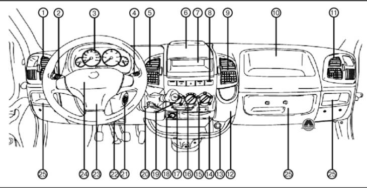
1. Боковые дефлекторы. 2. Левый подрулевой переключатель (указатели поворота). 3. Комбинация приборов. 4. Правый подрулевой переключатель (стеклоочистители ветрового стекла). 5. Центральные дефлекторы. 6. Полка (для письма/ чтения). 7. Отделение для аудиосистемы. 8. Кнопки центральной части панели приборов. 9. Центральные дефлекторы. 10. Отделение для мелких предметов/подушка безопасности пассажира. 11. Боковые дефлекторы. 12. Держатель для бутылки. 13. Электрическая розетка. 14. Пепельница. 15. Рукоятка изменения распределения воздушных потоков. 16. Рукоятка изменения температуры подаваемого в салон воздуха. 17. Рычаг включения режима рециркуляции. 18. Прикуриватель. 19. Рукоятка выбора режимов работы вентилятора. 20. Рычаг переключения передач. 21. Замок зажигания. 22. Рычаг фиксатора механизма регулировки рулевой колонки. 23. Звуковой сигнал. 24. Подушка безопасности. 25. Отделение для мелких предметов.
Примечание
Расположение контрольно-измерительных приборов, контрольных ламп и органов управления может изменяться в зависимости от модификации.
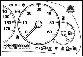
С ЛЕВОСТОРОННИМ РАСПОЛОЖЕНИЕМ ОРГАНОВ УПРАВЛЕНИЯ
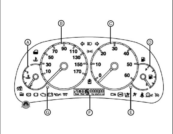
А. Указатель температуры охлаждающей жидкости. В. Спидометр. С. Тахометр. D. Указатель уровня топлива. Е. Установка счетчика пробега и напоминания о техническом обслуживании. F. Счетчик пробега. G. Установка часов.
С ПРАВОСТОРОННИМ РАСПОЛОЖЕНИЕМ ОРГАНОВ УПРАВЛЕНИЯ
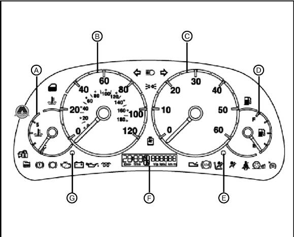
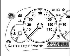
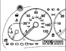
КОНТРОЛЬНО-ИЗМЕРИТЕЛЬНЫЕ ПРИБОРЫ
УКАЗАТЕЛЬ ТЕМПЕРАТУРЫ ОХЛАЖДАЮЩЕЙ ЖИДКОСТИ
В нормальных условиях стрелка должна находиться в средней части шкалы. Если она приближается к красному сектору, это означает, что двигатель перегружен и следует снизить нагрузку на него. Движение с высокой скоростью при высокой температуре наружного воздуха также приводит к приближению стрелки к красному сектору. В таком случае рекомендуется остановиться и заглушить двигатель. Через некоторое время можно вновь запустить двигатель и слегка нажать на педаль газа.
Примечание
Если ситуация не изменилась даже после принятия мер, заглушите двигатель и обратитесь к официальному дилеру Fiat для диагностики двигателя.
С левосторонним расположением органов управления
С правосторонним расположением органов управления
Примечание
Электронная система постепенно перекрывает подачу топлива во избежание превышения пороговой величины частоты вращения коленчатого вала двигателя.
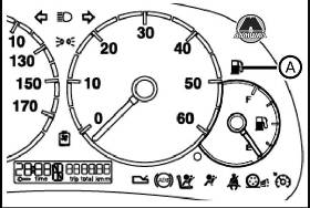
Когда загорается контрольная лампа низкого уровня топлива (А), это означает, что в топливном баке остается приблизительно 8-10 л топлива. Движение с почти пустым баком может привести к пропускам вспышек в цилиндрах и повреждению каталитического нейтрализатора.
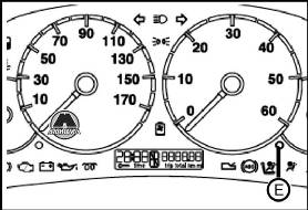
При нажатии кнопки (Е), на дисплее счетчика пробега последовательно отображаются следующие данные:
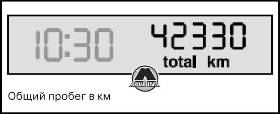
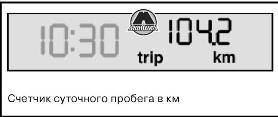
С помощью одной кнопки (Е) можно сбросить в 0 значение счетчика суточного пробега, а также выбрать режим работы счетчика пробега (общий или суточный пробег):
• если отображаются показания счетчика общего пробега, нажмите на кнопку менее чем на 2 с, после отпускания кнопки будет отображаться счетчик суточного пробега;
• если отображаются показания счетчика суточного пробега, нажмите на кнопку менее чем на 2 с, после отпускания кнопки будут отображаться показания счетчика общего пробега. Нажмите на кнопку более чем на 2 с для сброса показаний счетчика суточного пробега.
Установку времени можно производить, даже когда двигатель не работает, а ключ извлечен из замка зажигания.
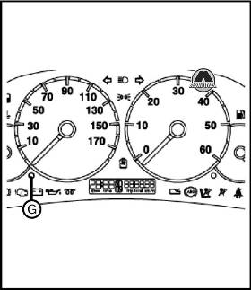
Показания часов изменяются на единицу при каждом нажатии и отпускании кнопки (G). При нажатии и удерживании кнопки в нажатом положении происходит быстрая смена показаний часов. Когда показания часов приближаются к требуемому значению, отпустите кнопку и завершите настройку вручную.
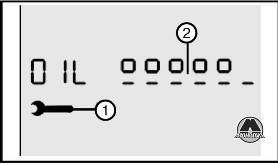
УКАЗАТЕЛЬ УРОВНЯ МОТОРНОГО МАСЛА (ДОПОЛНИТЕЛЬНОЕ ОБОРУДОВАНИЕ)
Указатель в графическом формате отображает уровень моторного масла между метками «MIN» и «МАХ». Для выполнения измерений установите автомобиль на ровную горизонтальную площадку, затем проделайте следующие операции:
1. Когда двигатель не работает, поверните ключ в замке зажигания в положение «MAR».
2. На дисплее будет отображаться слово «OIL» (МАСЛО) в течение 5 секунд вместе с шестью черточками и пятью или шестью квадратами, показывающими уровень моторного масла;
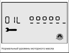
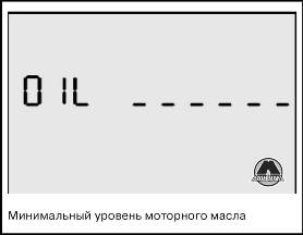
Если уровень масла минимальный, в кратчайшие сроки доведите уровень масла до нормы. В любом случае, перед доливкой масла проконтролируйте его уровень с помощью щупа.
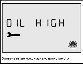
3. Если на дисплее отображаются слова «OIL HIGH», это означает, что уровень выше максимально допустимого и необходимо снизить уровень слива масла из поддона картера двигателя.
4. При запуске двигателя, во время выполнения измерения на индикаторе отобразится общий пробег или суточный пробег и время. Нажмите и отпустите кнопку (Е) для прекращения измерения; при этом на индикаторе отобразятся пробег и время.
ИНДИКАТОР ТЕХНИЧЕСКОГО ОБСЛУЖИВАНИЯ
Техническое обслуживание автомобиля должно производиться через каждые 15 000 км пробега, но не реже одного раза в год.
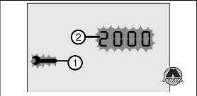
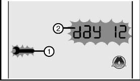
Напоминание (1) о необходимости очередного технического обслуживания отображается при поворачивании ключа в замке зажигания в положение «MAR», когда до очередного технического обслуживания остается 2 000 км пробега или 30 дней и повторяется через каждые 200 км (напоминание (2)),или один раз в три дня.
Примечание
Всегда соблюдайте сроки проведения технического обслуживания, указанные в «Графике технического обслуживания».
При каждом поворачивании ключа в замке зажигания в положение «MAR», контрольная лампа загорается приблизительно на 5 секунд. Индикатор технического обслуживания функционирует, только когда двигатель не работает, а ключ в замке зажигания находится в положении «MAR».
Когда ключ в замке зажигания находится в положении «MAR», отображается также символ индикатора технического обслуживания (1).
Интервалы технического обслуживания
Индикатор настроен на 20 000 км или 1 год. График технического обслуживания может быть изменен в зависимости от условий эксплуатации и типа установленного двигателя (бензиновый или дизельный). На дисплее отображаются следующие коды:
CFG 1 — 30 000 км и 365 дней для нормальных условий эксплуатации моделей с двигателями: бензиновыми 2.0 и дизельными 2.0 JTD, 2.8 JTD и 2.8 JTD POWER, и для тяжелых условий эксплуатации: дизельный двигатель 2.3 JTD.
CFG 2 — 20 000 км и 365 дней для тяжелых условий эксплуатации моделей с двигателями: бензиновым 2.0, дизельными 2.0 JTD, 2.8 JTD и 2.8 JTD POWER.
CFG 3 — 15 000 км и 365 дней для особо тяжелых условий эксплуатации модели с любыми типами двигателей.
Процедура конфигурирования
Для изменения периодичности технического обслуживания на неподвижном автомобиле поверните ключ в замке зажигания в положение «MAR» и нажмите на кнопку (Е) приблизительно на 10 секунд: на дисплее отобразится изображение гаечного ключа и надпись «CFG 1», «CFG 2» или «CFG 3».
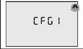
Нажмите и отпустите кнопку (Е) для выбора необходимой конфигурации, затем снова нажмите ее приблизительно на 5 секунд, чтобы сохранить новые межсервисные интервалы; на дисплее вновь отобразятся показания часов и пробег в км.
Пробег, оставшийся до технического обслуживания
2 000 км до следующего технического обслуживания
Когда до очередного технического обслуживания остается 2 000 пробега, при поворачивании ключа в замке зажигания в положение «MAR» отобразится индикатор технического обслуживания (знак гаечного ключа), после чего в течение 5 секунд будет отображаться оставшееся количество километров пробега или количество дней, оставшихся до наступления срока очередного технического обслуживания.
Затем, через 5 секунд, индикатор вернется в режим отображения счетчика пробега. Сначала отображается информация о плановом техническом обслуживании — пробег (в км) или дни. Обратитесь на станцию технического обслуживания Fiat для проведения технического обслуживания и сброса индикатора технического обслуживания.
Примечание
Рекомендуется обращаться на станцию технического обслуживания Fiat сразу после получения предупреждения о следующем техническом обслуживании.
При следующем запуске появится изображение гаечного ключа (1), и контрольная лампа загорится на 5 секунд, а на дисплее снова отобразятся время и пробег.
При достижении установленного значения пробега: при повороте ключа в замке зажигания в положение «MAR» индикатор (1) загорится на 5 секунд одновременно с индикацией пробега («0 км»), оставшегося до очередного технического обслуживания. Затем через 5 секунд индикатор (2) вернется в режим отображения показаний счетчика общего или суточного пробега.
Контрольная лампа загорается в следующих случаях:
АККУМУЛЯТОРНАЯ БАТАРЕЯ НЕ ЗАРЯЖАЕТСЯ (КРАСНЫЙ ЦВЕТ ЛАМПЫ)
При наличии неисправности в бортовой сети. Лампа загорается при поворачивании ключа в замке зажигания в положение «MAR» и гаснет при запуске двигателя. Допускается некоторая задержка, если двигатель работает на оборотах холостого хода. Обратитесь на станцию технического обслуживания Fiat в кратчайшие сроки для предотвращения разряда аккумуляторной батареи.
АВАРИЙНОЕ ДАВЛЕНИЕ МАСЛА В СИСТЕМЕ СМАЗКИ ДВИГАТЕЛЯ (КРАСНЫЙ ЦВЕТ ЛАМПЫ)
При снижении давления моторного масла ниже допустимого уровня. Лампа загорается при поворачивании ключа в замке зажигания в положение «MAR» и гаснет при запуске двигателя. Допускается некоторая задержка, если двигатель работает на оборотах холостого хода. Если двигатель сильно нагружен, то на оборотах холостого хода лампа может мигать. Однако при легком нажатии акселератора она погаснет.
ВНИМАНИЕ
Если контрольная лампа горит при движении автомобиля, остановите двигатель и обратитесь на станцию технического обслуживания Fiat.
АНТИПРОБУКСОВОЧНАЯ СИСТЕМА (ASR) (ЖЕЛТЫЙ ЦВЕТ ЛАМПЫ)
При поворачивании ключа в замке зажигания в положение «MAR» загорится контрольная лампа, которая должна погаснуть через несколько секунд. Контрольная лампа мигает при движении автомобиля, чтобы предупредить водителя об активации системы. При отключении системы с помощью специальной кнопки, контрольная лампа горит постоянно. При включенной ASR и выявлении неисправности системы, контрольная лампа горит постоянно. Проверьте правильность этой информации, нажав на кнопку один раз (при этом, если система функционирует нормально, контрольная лампа погаснет, в то время как при обнаружении неисправности останется включенной). В данной ситуации немедленно свяжитесь с официальным дилером компании Fiat.
ОТКЛЮЧЕНИЕ ПОДУШКИ БЕЗОПАСНОСТИ ПЕРЕДНЕГО ПАССАЖИРА (ЖЕЛТЫЙ ЦВЕТ ЛАМПЫ)
При отключении подушки безопасности переднего пассажира соответствующим кнопочным выключателем.
ВНИМАНИЕ
Контрольная лампа обозначает также неисправность контрольной лампы. Она отображается прерывистым миганием контрольной лампы дольше 4 секунд. При этом контрольная лампа не будет включаться, если обнаружится неисправность системы безопасности. Остановите автомобиль и обратитесь на станцию технического обслуживания Fiat для диагностики системы.
НЕИСПРАВНОСТЬ СИСТЕМЫ ДИАГНОСТИКИ (EOBD) (ТОЛЬКО ДЛЯ БЕНЗИНОВЫХ ДВИГАТЕЛЕЙ) (ЖЕЛТЫЙ ЦВЕТ ЛАМПЫ)
При нормальном функционировании двигателя при поворачивании ключа в замке зажигания в положение «MAR», загорится контрольная лампа, которая должна погаснуть после запуска двигателя. Включение контрольной лампы свидетельствует о том, что она функционирует правильно. Если контрольная лампа загорается во время движения:
1. Горит постоянно — предупреждение о неисправности системы подачи топлива/зажигания, которая может привести к увеличению токсичности отработавших газов, снижению мощности, ухудшению управляемости и увеличению расхода топлива.
В таких случаях можно продолжать движение, но не следует перегружать двигатель и двигаться на невысокой скорости. Продолжительная работа двигателя с горящей контрольной лампой может, в результате, привести к выходу его из строя. Немедленно свяжитесь с официальным дилером компании Fiat.
Контрольная лампа погаснет, как только неисправность исчезнет. Однако код ошибки будет сохранен в памяти.
2. Мигает — предупреждение о возможности повреждения каталитического нейтрализатора. Если лампа мигает, необходимо плавно снизить обороты двигателя, пока лампа не перестанет мигать. Продолжайте движение на невысокой скорости. Старайтесь избегать режимов работы двигателя, при которых лампа снова начнет мигать. Необходимо в кратчайшие сроки обратиться на станцию технического обслуживания Fiat.
Примечание
Необходимо в кратчайшие сроки обратиться на станцию технического обслуживания Fiat, если контрольная лампа не загорается при повороте ключа в положение «MAR» или загорается во время движения. Причины включения контрольной лампы могут быть установлены с помощью специального оборудования. Всегда соблюдайте правила дорожного движения страны, в которой находитесь.
НЕИСПРАВНОСТЬ СИСТЕМЫ ПОДАЧИ ТОПЛИВА (ДИЗЕЛЬНЫЕ ДВИГАТЕЛИ) (КРАСНЫЙ ЦВЕТ ЛАМПЫ)
При возникновении неисправности в системе подачи топлива. Контрольная лампа должна загореться при повороте ключа зажигания в положение «MAR» и погаснуть через несколько секунд. Контрольная лампа загорается во время движения, сигнализируя о неправильной работе системы подачи топлива, при этом возможно снижение мощности, управляемости и увеличение расхода топлива. В таких случаях можно продолжать движение, но не следует допускать большой нагрузки на двигатель при высоких скоростях. Необходимо в кратчайшие сроки обратиться на станцию технического обслуживания Fiat. Длительное использование автомобиля с горящей контрольной лампой может привести к повреждению двигателя, особенно, если происходят пропуски вспышек в цилиндрах. Допускается только кратковременное использование автомобиля, при этом скорость движения не должна быть высокой. Кратковременное включение контрольной лампы не должно вызывать беспокойство.
ВЫСОКАЯ ТЕМПЕРАТУРА РАБОЧЕЙ ЖИДКОСТИ АВТОМАТИЧЕСКОЙ ТРАНСМИССИИ (КРАСНЫЙ ЦВЕТ ЛАМПЫ)
При поворачивании ключа в замке зажигания в положение «MAR», загорится контрольная лампа, но она должна погаснуть через 4 секунды. Если лампа мигает, это сигнализирует о неисправности в трансмиссии, если горит постоянно — о слишком высокой температуре рабочей жидкости в автоматической трансмиссии.
• Горит постоянно — слишком высокая температура рабочей жидкости автоматической трансмиссии.
Контрольная лампа мигает и горит постоянно во время движения, указывая, что температура рабочей жидкости достигла максимально допустимого значения. В таком случае необходимо остановить автомобиль, перевести рычаг селектора в положение «N» или «Р» и оставить двигатель работать на оборотах холостого хода (дождаться включения вентиляторов системы охлаждения двигателя), пока контрольная лампа не погаснет. После этого можно продолжать движение, избегая высоких нагрузок.
При повторном включении контрольной лампы остановите автомобиль, оставьте двигатель работать на оборотах холостого хода и дождитесь, пока контрольная лампа погаснет.
Если контрольная лампа загорится вновь раньше чем через 15 мин, остановите автомобиль, не глушите двигатель и дождитесь охлаждения двигателя и трансмиссии с помощью вентиляторов системы охлаждения.
• Мигает — неисправность автоматической трансмиссии.
Контрольная лампа, мигающая при запуске двигателя или во время движения, указывает на наличие неисправности автоматической трансмиссии. Включите 3-ю передачу, и автоматическая система управления перейдет в аварийный режим работы. При выключении и повторном включении двигателя, система самотестирования может не допустить неисправность, и контрольная лампа выключится. Однако, код неисправности будет сохранен в памяти, в этом случае необходимо обратиться на станцию технического обслуживания Fiat для диагностики системы.
УРОВЕНЬ ОХЛАЖДАЮЩЕЙ ЖИДКОСТИ (КРАСНЫЙ ЦВЕТ ЛАМПЫ) (ДОПОЛНИТЕЛЬНОЕ ОБОРУДОВАНИЕ)
Загорается, когда уровень охлаждающей жидкости в радиаторе опускается ниже минимально допустимого уровня.
ВЫСОКАЯ ТЕМПЕРАТУРА ОХЛАЖДАЮЩЕЙ ЖИДКОСТИ (КРАСНЫЙ ЦВЕТ ЛАМПЫ)
Загорается, когда температура охлаждающей жидкости в системе охлаждения двигателя превышает максимально допустимую величину.
НЕИСПРАВНОСТЬ ПОДУШКИ БЕЗОПАСНОСТИ (КРАСНЫЙ ЦВЕТ ЛАМПЫ) (ДОПОЛНИТЕЛЬНОЕ ОБОРУДОВАНИЕ)
Контрольная лампа загорается при неисправности в системе подушек безопасности.
ВНИМАНИЕ
Если при поворачивании ключа в замке зажигания в положение «MAR» контрольная лампа ft не загорается или загорается при движении, это может указывать на наличие неисправности в системе безопасности; при этом подушки безопасности и аварийные натяжители ремней безопасности могут не активироваться при столкновении или сработать неожиданно. Немедленно остановите автомобиль и обратитесь на станцию технического обслуживания Fiat для диагностики системы.
РЫЧАГ СТОЯНОЧНОГО ТОРМОЗА ВЗВЕДЕН/НИЗКИЙ УРОВЕНЬ ТОРМОЗНОЙ ЖИДКОСТИ (КРАСНЫЙ ЦВЕТ ЛАМПЫ)
Лампа может загораться в таких случаях:
• когда взведен рычаг стояночного тормоза;
• когда уровень тормозной жидкости опускается ниже минимально допустимого уровня;
• в сочетании с горящей контрольной лампой системы распределения тормозных сил (EBD).
ВНИМАНИЕ
Если во время движения загорается контрольная лампа, проверьте, взведен ли рычаг стояночного тормоза. Если контрольная лампа загорается при опущенном рычаге стояночного тормоза, немедленно остановите автомобиль и обратитесь на станцию технического обслуживания Fiat.
РЕМНИ БЕЗОПАСНОСТИ (КРАСНЫЙ ЦВЕТ ЛАМПЫ) (ДЛЯ НЕКОТОРЫХ СТРАН)
Загорается, когда не пристегнут ремень безопасности водителя.
ДВЕРИ ОТКРЫТЫ (КРАСНЫЙ ЦВЕТ ЛАМПЫ)
Загорается, когда не закрыта одна из дверей.
Примечание
Контрольная лампа имеется лишь в некоторых модификациях.
ИЗНОС ПЕРЕДНИХ ТОРМОЗНЫХ КОЛОДОК (КРАСНЫЙ ЦВЕТ ЛАМПЫ)
Загорается, когда износ накладок передних тормозных колодок достиг предельно допустимой величины. Замените колодки и проверьте состояние задних тормозных колодок.
СИСТЕМА FIAT CODE (ЖЕЛТАЯ)
Контрольная лампа загорается в следующих случаях (ключ в замке зажигания в положении «MAR»):
1. Однократное мигание при распознавании кода ключа. Разрешен запуск двигателя.
2. Горит постоянно — код ключа не распознан. Выполните процедуру аварийного пуска двигателя.
3. Мигает — автомобиль не защищен системой электронной блокировки запуска двигателя (FIAT CODE). Запуск двигателя возможен.
СЛИВ ВОДЫ ИЗ ТОПЛИВНОГО ФИЛЬТРА (ТОЛЬКО МОДЕЛИ С ДИЗЕЛЬНЫМИ ДВИГАТЕЛЯМИ) (ЖЕЛТЫЙ ЦВЕТ ЛАМПЫ)
Контрольная лампа загорается при накоплении воды в топливном фильтре. Контрольная лампа должна загореться при повороте ключа зажигания в положение «MAR» и погаснуть через несколько секунд.
ВНИМАНИЕ
Наличие воды в дизельном топливе может привести к серьезным повреждениям системы подачи топлива. При включении контрольной лампы необходимо срочно обратиться на станцию технического обслуживания Fiat для диагностики системы. Контрольная лампа, загоревшаяся сразу же после заправки топливом, может свидетельствовать о наличии воды в топливном баке: в этом случае следует заглушить двигатель и связаться с официальным дилером компании Fiat.
НЕИСПРАВНОСТЬ СИСТЕМЫ АНТИБЛОКИРОВКИ ТОРМОЗОВ (ABS) (ЖЕЛТЫЙ ЦВЕТ ЛАМПЫ)
Контрольная лампа загорается при возникновении неисправности ABS. При этом обычная тормозная система продолжает функционировать без участия ABS, необходимо немедленно обратиться на станцию технического обслуживания Fiat. Контрольная лампа должна загореться при поворачивании ключа в замке зажигания в положение «MAR» и погаснуть приблизительно через 2 секунды.
ВНИМАНИЕ
Автомобили с ABS, оборудованные электронной системой распределения тормозных усилий (EBD). Контрольные лампы загораются одновременно при работе двигателя, свидетельствуя о неисправности системы EBD. В случае резкого торможения, задние колеса могут оказаться заблокированными слишком рано, что может стать причиной заноса. Соблюдая осторожность, двигайтесь на станцию технического обслуживания Fiat для диагностики системы.
ВНИМАНИЕ
Если при работающем двигателе горит только контрольная лампа, это обычно сигнализирует только о неисправности ABS. В этом случае рабочая тормозная система продолжает функционировать, однако ABS не работает. При этом эффективность работы системы EBD может быть снижена. Рекомендуется, избегая резких торможений, двигаться на станцию технического обслуживания Fiat.
ЗАДНИЕ ПРОТИВОТУМАННЫЕ ФОНАРИ (ЖЕЛТЫЙ ЦВЕТ ЛАМПЫ)
Загорается при включении задних противотуманных фонарей.
СВЕЧИ НАКАЛИВАНИЯ (ЖЕЛТЫЙ ЦВЕТ ЛАМПЫ) (ТОЛЬКО МОДЕЛИ С ДИЗЕЛЬНЫМИ ДВИГАТЕЛЯМИ)
Контрольная лампа загорается при поворачивании ключа в замке зажигания в положение «MAR». Лампа погаснет, когда свечи накаливания разогреются до требуемой температуры.
УКАЗАТЕЛИ ПОВОРОТА (ПРОБЛЕСКОВЫЙ РЕЖИМ) (ЗЕЛЕНЫЙ ЦВЕТ ЛАМПЫ)
Загораются при включении указателей с помощью левого подрулевого переключателя.
КРУИЗ-КОНТРОЛЬ (ЗЕЛЕНЫЙ ЦВЕТ ЛАМПЫ)
Загорается при включении круизконтроля (при нажатой кнопке «ON»).
ВНЕШНИЕ СВЕТОВЫЕ ПРИБОРЫ (ЗЕЛЕНЫЙ ЦВЕТ ЛАМПЫ)
Загорается при включении габаритных огней и ближнего света фар.
ДАЛЬНИЙ СВЕТ ФАР (СИНИЙ ЦВЕТ ЛАМПЫ)
Загорается при включении дальнего света фар.
ЛЕВЫЙ ПОДРУЛЕВОЙ ПЕРЕКЛЮЧАТЕЛЬ
Левый комбинированный подрулевой переключатель осуществляет управление внешними световыми приборами. Внешние световые приборы могут функционировать, только когда ключ в замке зажигания находится в положении «MAR». Подсветка панели приборов и органов управления системой отопления/вентиляции (или кондиционером), а также прикуривателя, включается при включении габаритных огней.
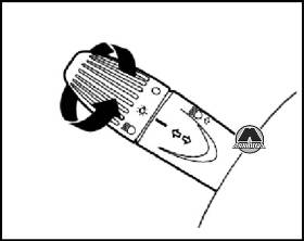
Для включения огней переведите поворотный переключатель положение. На панели приборов загорится контрольная лампа.
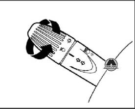
Поверните поворотный переключатель из положения в положение.
Примечание
Ближний свет фар автоматически выключается при включении дальнего света фар, если включены противотуманные фары.
Для включения дальнего света фар отожмите рычаг из положения в направлении панели приборов. На панели приборов загорится контрольная лампа. Для выключения фар потяните рычаг в направлении рулевого колеса.
Кратковременное включение дальнего света
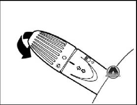
Для кратковременного включения дальнего света потяните рычаг к рулевому колесу (не фиксированное положение).
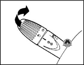
Перемещайте рычаг следующим образом:
вверх — для включения указателей правого поворота;
вниз — для включения указателей левого поворота.
На панели приборов начнет мигать контрольная лампа.
Указатели поворотов отключаются автоматически при возвращении рулевого колеса в положение, соответствующее прямолинейному движению. Если вы хотите кратковременно включить указатели поворота (например, при перестроении из ряда в ряд), отклоните рычаг вверх или вниз (не переводя его в фиксированное положение). При отпускании, рычаг вернется в нейтральное положение.
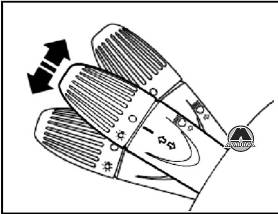
ПРАВЫЙ ПОДРУЛЕВОЙ ПЕРЕКЛЮЧАТЕЛЬ
Стеклоочистители/омыватели ветрового стекла
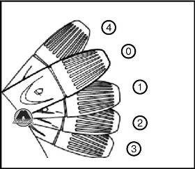
Стеклоочистители и омыватели функционируют, только когда ключ в замке зажигания находится в положении «MAR».
Положения:
0 — стеклоочистители ветрового стекла отключены;
1 — интервальный режим работы стеклоочистителей;
2 — низкая скорость стеклоочистителей;
3 — высокая скорость стеклоочистителей;
4 — нефиксированное положение: при отпускании переключателя, он возвращается в положение 0.
ЛОГИЧЕСКОЕ УПРАВЛЕНИЕ ОМЫВАНИЕМ
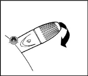
Чтобы направить струю омывающей жидкости на ветровое стекло и включить стеклоочистители одним движением, потяните рычаг левого подрулевого переключателя к рулевому колесу. Стеклоочиститель будет функционировать автоматически при удерживании рычага омывателя дольше половины секунды. После отпускания рычага, щетки стеклоочистителя совершат три двойных хода. Чтобы включить омыватель несколько раз без включения стеклоочистителей, быстро (менее чем на полсекунды) потяните рычаг несколько раз.
Светильники включаются автоматически при открывании двери.
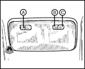
Нажмите на кнопку (А) для включения обеих ламп при закрытых или открытых дверях.
Нажмите на кнопку (С), чтобы включить только правую лампу. Нажмите на кнопку (В), чтобы включить только левую лампу.
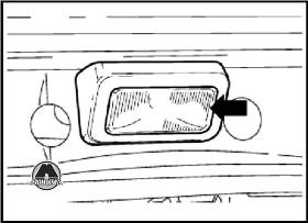
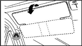
Второй потолочный светильник находится над дверью багажного отсека. Для включения этого светильника нажмите на область пластмассового плафона, указанную стрелкой, см. рисунок.
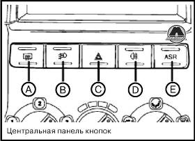
А — кнопка вкл./выкл. обогрева заднего стекла (дополнительное оборудование).
Когда включен обогрев заднего стекла, также включается обогрев наружных зеркал заднего вида. Можно также включить обогрев наружных зеркал заднего вида без включения обогрева заднего стекла: с помощью той же кнопки.
В — кнопка вкл./выкл. противотуманных фар.
С — кнопка вкл./выкл. аварийной сигнализации.
При нажатии кнопки вне зависимости от положения ключа в замке зажигания будут активированы в проблесковом режиме все указатели поворотов и контрольные лампы на панели приборов.
ВНИМАНИЕ
При пользовании аварийной сигнализацией следуйте правилам дорожного движения той страны, в которой находитесь.
D — кнопка вкл./выкл. задних противотуманных фонарей.
Е — кнопка вкл./выкл. антипробуксовочной системы (ASR).
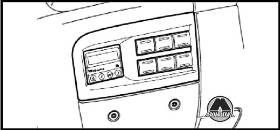
Панель кнопок имеется в модификациях Minibus, Ambulance и на полноприводных модификациях. С помощью кнопок, расположенных на этой панели, осуществляется управление дополнительным оборудованием.
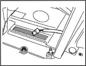
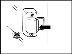
ВЫКЛЮЧАТЕЛЬ ПОДАЧИ ТОПЛИВА
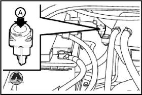
Выключатель подачи топлива расположен на щите моторного отсека и при дорожно-транспортном происшествии перекрывает подачу топлива, тем самым останавливая работу двигателя.
ВНИМАНИЕ
Если после дорожно-транспортного происшествия обнаружены утечки или ощущается запах топлива, во избежание возгорания не включайте этот выключатель.
Осмотрите моторный отсек, топливный бак на наличие утечки топлива, а поверхность под автомобилем на наличие следов утечки. Если утечки топлива не обнаружены и автомобиль способен продолжать движение, нажмите на кнопку (А) для включения подачи топлива. Не забудьте повернуть ключ в замке зажигания в положение «STOP» для предотвращения разрядки аккумуляторной батареи.
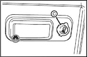
ОТКЛЮЧЕНИЕ АККУМУЛЯТОРНОЙ БАТАРЕИ
Автомобиль оборудован устройством отключения аккумуляторной батареи, встроенным в блок управления (СВА), расположенным над положительным выводом аккумуляторной батареи, работающим совместно с инерционным выключателем подачи топлива и отключением питания стартера. Если двигатель автомобиля можно запустить после дорожно-транспортного происшествия, для восстановления подключения аккумуляторной батареи необходимо нажать на желтую кнопку.
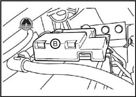
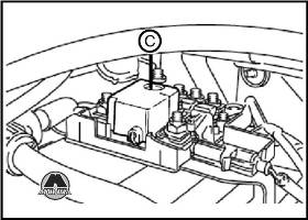
Для восстановления подключения аккумуляторной батареи снимите крышку (В) и нажмите на желтую кнопку (С) блока, расположенного над положительным выводом аккумуляторной батареи.
ПЕРЧАТОЧНЫЙ ЯЩИК/ОТДЕЛЕНИЕ ДЛЯ МЕЛКИХ ПРЕДМЕТОВ
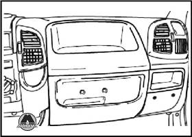
В правой части панели приборов находятся отделения для мелких предметов различных размеров, предназначенные для хранения документов, бумаг и т. п. В некоторых модификациях крышка перчаточного ящика может оснащаться замком, запираемым с помощью ключа зажигания.
На центральной части панели приборов расположен держатель для бутылки.
В модификациях с тремя сиденьями в кабине, под сиденье пассажира может устанавливаться корзина для мелких предметов или бумаг.
На панелях облицовки дверей могут располагаться карманы и дополнительный держатель для бутылки.
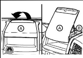
В средней части панели приборов над отделением для аудиосистемы располагается подвижная полка для письма (А), которую можно использовать и для чтения, подняв ее заднюю часть и оперев на панель приборов (В).
Примечание
Не устанавливайте полку для письма в вертикальное положение во время движения.
В кабине, оборудованной двумя пассажирскими сиденьями, можно использовать специальную подставку.
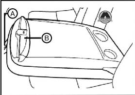
Она расположена в верхней части спинки центрального сиденья; чтобы разложить ее, потяните за ленту (А) и вытяните спинку вперед. Прижим (В) служит для закрепления листов бумаги.
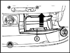
ВЕЩЕВОЙ ЯЩИК/ОХЛАЖДАЕМЫЙ ЯЩИК ДЛЯ ПРОДУКТОВ
Дополнительный ящик может быть установлен в кабине между сиденьем водителя и одиночным сиденьем пассажира и иметь одно из двух возможных исполнений: ящик для вещей или охлаждаемый ящик для продуктов.
Объем ящика для вещей около 12 л, в нем возможна перевозка портативного компьютера средних размеров. Снаружи располагается карман для бумаг, держатель полуторалитровой пластиковой бутылки и подстаканник.
В наклоненном положении крышка ящика, оборудованная зажимом для бумаг, может использоваться для письма/чтения.
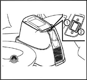
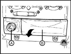
Охлаждаемый ящик для продуктов
Охлаждаемый ящик для продуктов объемом около 12 л может использоваться для перевозки двух полуторалитровых пластиковых бутылок. Охлаждаемый ящик теплоизолирован и подключен к электрическому устройству, осуществляющему охлаждение или подогрев внутреннего объема ящика. Ящик можно использовать для хранения пищевых продуктов. Продукты должны быть надлежащим образом упакованы во избежание непосредственного контакта с внутренними стенками ящика. При включенном охлаждении, через некоторое время разность температур между температурой в салоне и внутри ящика может достигать 18°С (при плотно закрытой крышке). Однако, при любых условиях не может быть достигнута температура ниже 8-10°С.
Во избежание разряда аккумуляторной батареи, система подключена через замок зажигания; следовательно, охлаждение может осуществляться только при работающем двигателе. Если стоянка автомобиля продлится дольше 2-х часов, из ящика следует вынуть скоропортящиеся продукты. Для обеспечения нормального функционирования не следует перекрывать вентиляционные решетки, расположенные на внутренней стенке ящика.
Переведите переключатель в положение:
(1) — для включения режима подогрева (загорится красный светодиод);
(2) — для включения режима охлаждения (загорится зеленый светодиод).
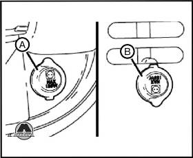
Автомобиль оборудован электрической розеткой (А), расположенной на панели приборов (рядом с центральным отделением для мелких предметов) и электрической розеткой (В) (только для модификации Van), расположенной на правой стойке задней двери.
Модификации Panorama оснащены электрической розеткой (С), расположенной рядом с боковой сдвижной дверью. Напряжение на обе электрические розетки подается при поворачивании ключа в замке зажигания в положение «MAR».
ВНИМАНИЕ
Не пользуйтесь розетками для подключения устройств, мощность которых превышает 180 Вт (максимальная сила тока 15 А).Примечание
Длительное (более часа) использование мощных электрических устройств, когда ключ находится в положении «MAR», а двигатель на работает, может стать причиной разряда аккумуляторной батареи и привести к невозможности последующего запуска двигателя.
Правильное функционирование обеспечивается, только если устройства оснащены сертифицированным штекером, подобным устанавливаемым на компонентах линейки аксессуаров Fiat.
РАЗЪЕМ ДЛЯ СПЕЦАВТОМОБИЛЕЙ
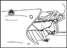
Под подставкой для ног находится специальный разъем, предназначенный для использования компаниями, осуществляющими переоборудование автомобилей (с установкой дополнительной аккумуляторной батареи) с целью создания специальных модификаций, например, автомобилей скорой помощи, мобильных офисов и т. д.
ПЕПЕЛЬНИЦА И ПРИКУРИВАТЕЛЬ
1. Чтобы воспользоваться прикуривателем, нажмите на кнопку (А).
Приблизительно через 15 секунд он автоматически вернется в исходное положение и будет готов к использованию.
2. Откройте крышку (В) в направлении стрелки.
ВНИМАНИЕ
Прикуриватель нагревается до очень высокой температуры. При обращении с ним соблюдайте особую осторожность, убедитесь, что исключена возможность попадания прикуривателя в руки детей: это может стать причиной возгорания и/или ожогов.ВНИМАНИЕ
Не бросайте в пепельницу бумагу: контакт с горящими сигаретами может привести к возгоранию.Примечание
Не используйте прикуриватель в качестве электрической розетки — это может привести к его повреждению! Для этих целей (в том числе для зарядки мобильных телефонов) пользуйтесь только розетками (А, В или С — на рисунке).
Солнцезащитные козырьки располагаются по обе стороны от внутреннего зеркала заднего вида. Они могут только подниматься или опускаться. Солнцезащитные козырьки как водителя, так и пассажира, с задней стороны оснащены карманом для документов, а также инструкцией по устранению запотевания стекол.
ЦЕНТРАЛЬНЫЕ БОКОВЫЕ ЗАДНИЕ СТЕКЛА (МОДИФИКАЦИИ PANORAMA И COMBI)
Центральные боковые задние стекла могут перемещаться в горизонтальном направлении. Для открывания окон служит ручка, показанная на рисунке.
- Manuals
- Brands
- Fiat Manuals
- Automobile
- Ducato 2021
- Owner’s handbook manual
-
Contents
-
Table of Contents
-
Bookmarks
Quick Links
F
I
A
T
D
U
C
A
T
O
O
W
N
E
R
H
A
N
D
B
O
O
K
Related Manuals for Fiat Ducato 2021
Summary of Contents for Fiat Ducato 2021
-
Page 3
Dear Customer, We would like to congratulate and thank you for choosing a Fiat Ducato. We have written this handbook to help you get to know all the features of your vehicle and use it in the best possible way. You should read it right through before taking to the road for the first time. -
Page 4
If, after buying the vehicle, you decide to add electrical accessories (with the risk of gradually draining the battery), visit a Fiat Dealership. They can calculate the overall electrical requirement and check that the electrical system of the vehicle can support the required load. -
Page 5
GRAPHICAL INDEX KNOWING YOUR VEHICLE KNOWING THE INSTRUMENT PANEL SAFETY STARTING AND DRIVING IN CASE OF EMERGENCY SERVICING AND MAINTENANCE TECHNICAL SPECIFICATIONS MULTIMEDIA CONTENTS… -
Page 7
GRAPHICAL INDEX 3/4 front F1A5000 Changing a wheel ..HEADLIGHTS WINDSCREEN WIPER Fix&Go tyre repair kit ..Bulb types ….Operation . -
Page 8
3/4 rear F1A5001 REAR LIGHTS Bulb types ….Bulb replacement ..LOAD COMPARTMENT Opening/closing … THIRD BRAKE LIGHT Bulb types . -
Page 9
Dashboard (versions with 7″ and 10″ Uconnect™ system) F1A0673 Interior fittings … . Heated rear window ..AIR VENTS Front airbag … . . Lane Control System . -
Page 10
Dashboard (versions with Uconnect™ Radio 5″ system) F1A0684 Interior fittings … . Heated rear window ..AIR VENTS Front airbag … . . Lane Control System . -
Page 11
Interior F1A0601 BONNET OPENING LEVER SEATS Opening/closing … Adjustments ….Sprung seat ….CONTROL PANEL Seats with adjustable armrests . -
Page 12
The handbook that you are reading ALTERATIONS……11 HEAD RESTRAINTS ….. 69 simply and directly explains how it is THE FIAT CODE SYSTEM ….. 11 INTERIOR FITTINGS ….. 69 made and how it works. THE KEYS……..12 TACHOGRAPH ……76 That’s why we advise you to read it… -
Page 13
(for example The code is sent only if the Fiat CODE due to a voltage drop). system control unit has recognised the If the icon/warning light stays on, code transmitted from the key. -
Page 14
Versions with «Keyless Go» system the lock on the dashboard drawer; IMPORTANT the battery disconnect switch. On versions equipped with the «Keyless Go» system, the vehicle is fitted with a Version with 3 sensors 1) The electronic components inside mechanical key. Press button (B) fig. -
Page 15
Door lock and load compartment 3 seconds. The LED will flash more slowly when the alarm is on. Briefly press the «FIAT» / button: locking of doors and load compartment F1A0603 with ceiling light off and single flash of… -
Page 16
For vehicles with keys with remote REPLACING THE control , if one or more doors are open, ELECTRONIC KEY BATTERY the doors will not be locked. To replace the battery, proceed as This situation is indicated by a rapid follows: flashing of the direction indicators (where provided). -
Page 17
2 hours Fiat Dealership, which will take care of their and cause death. Keep new and used disposal. -
Page 18
“Display” chapter, where provided, and The ignition device has the following repeated. contact the Fiat Dealership as soon as possible states: possible. For more information on the STOP: engine off, steering column 3) 4) 5) 6) engine start-up, see the description in locked. -
Page 19
(e.g. attempted theft), have it checked ignition device is pressed and the start the vehicle. over by a Fiat Dealership before driving 9) Never extract the mechanical key while electronic key is recognised. again. -
Page 20
WARNING The engine stop function is bonnet are correctly closed, a fault guaranteed by the Fiat CODE, which versions with the message on the… -
Page 21
3 seconds. With the function on, the the instrument panel” section). button (A) fig. 24 is disabled. Double-tapping on the «FIAT» / DISARMING THE ALARM button on the remote control activates To permanently disable the alarm (e.g. the dead lock device (see «Dead lock»… -
Page 22
If a power supply is not present (blown fuse, battery disconnected, etc.) it is, however, possible to lock the doors manually. While travelling, at speeds exceeding 20 km/h, all the doors will be locked automatically if the function was selected in the Setup menu. PASSIVE ENTRY/KEYLESS F1A0603… -
Page 23
Door locking / unlocking The vehicle doors can be locked WARNING To avoid leaving the anyway pressing the button on the electronic key inside the vehicle To lock/unlock the doors, proceed as electronic key or on the inner panel. accidentally, the Passive Entry/Keyless follows: Entry function features an automatic make sure that you have the… -
Page 24
After closing the doors of the load through the display Menu or the Notes compartment, the alarm system will be Uconnect™ system. The vehicle will unlock the doors if one reactivated again. of the following conditions is met: MECHANICAL LOCK the doors were closed by pressing OF PASSENGER SIDE WARNING If only the load… -
Page 25
compartment or centralised) or an presses on the button on the key unlocking request from the remote with remote control fig. 23. control/door latch or by using the For vehicles equipped with the Passive Passive Entry/Keyless Entry. Entry/Keyless Entry system, Dead Lock is activated every time the vehicle is locked using the button on the outside handle. -
Page 26
SLIDING SIDE DOOR Position (1): Device not engaged (door may be opened from the inside); 12) 13) Position (2): Device engaged (door To open the sliding side door, lift the locked). handle (A) fig. 29 and accompany the The device stays on even if the doors door in the opening direction. -
Page 27
Manual opening of the second swing door Pull the lever (C) fig. 34 in the direction indicated by the arrow. The double rear swing doors have two opening positions: the first to an angle of approximately 90° and the second is approximately 180°;… -
Page 28
REAR FOOTBOARD disengaged only by inserting the key instrument panel display if it is not fully (for goods carrier van versions) metal insert in either of the door locks as retracted in the same way as if the rear described previously: in this case the doors are not shut. -
Page 29
SEATS weight off the part of the seat that must be lowered. Backrest angle adjustment Turn knob (D) fig. 38. Longitudinal adjustment Lift lever (A) fig. 38 and push the seat Lumbar adjustment forwards or backwards: in the driving Operate the knob (E) fig. 39 to adjust. position, you should be able to rest your arms on the rim of the steering wheel. -
Page 30
the seat on the opposite side. Operate their adjustment, see the «Seats with the control (A) fig. 43 to turn the seat. adjustable armrests» paragraph) and Before turning the seat, it must be a head restraint with adjustable height moved forward and only then adjusted (adjusting it, see the «head restraints»… -
Page 31
Height adjustment adjustments (revolving or fixed, with seat belt, etc.) or heated. Operate the controls (B) fig. 46 or (C) fig. 46 to raise or lover the front/rear For the various adjustments refer to part of the seat, respectively. what is described in the previous paragraph «Revolving seat with seat Seat rotation belt»). -
Page 32
EAT&WORK TABLE no buttons need to be pressed to compartment fig. 53 located behind the return to the closed position. It will be (for versions/markets, where provided) cab. sufficient to push in the area indicated The seat is equipped with a folding by the arrow fig. -
Page 33
When the seat is restored to its normal position, it engages with the retaining device without the need to operate the lever again. On the one-piece Panorama seat in the second row both side seats are fixed. Folding middle seat backrest (2 nd — 3 rd row) Lift the lever (C) fig. -
Page 34
F1A0710 F1A0712 F1A0035 remove the plastic casing of the disconnect the connector fig. 62; – turn the backrest 5° towards the rear benches fig. 60; area; – fold the backrest forward with your left hand. F1A0713 F1A0711 lift the lever (A), tilt the backrest undo the screws (C) and (D) and forward into the Easy Entry position and pull out the head restraints fig. -
Page 35
lift the lever (A) (movement 3), over the retaining slider (C) fig. 68 (on the side) which holds the system in raised position during the operations. When the base has been locked, it will be possible to move the seat by accompanying it with both hands to move it forwards or backwards fig. -
Page 36
4-SEATER BENCH the holes in the tracks; in that position push the latch lever downwards (easily found by sliding the base a little SEAT (Crew Cab Van fig. 71 with sufficient force, until the and simultaneously pulling it out) the versions) system locks. -
Page 37
contents of the adhesive plate located WARNING under the bench. 22) All adjustments must be made with the IMPORTANT vehicle stationary. 23) After releasing the adjustment lever, always check that the seat is locked on 6) The fabric upholstery of your vehicle is the guides by trying to move it back and designed to withstand the normal wear forth. -
Page 38
REAR-VIEW If the display is difficult to see, clean the camera fig. 77. If snow, ice, mud MIRRORS or other foreign matter obstruct the INTERIOR MIRROR camera lens, clean it with water and Lever (A) fig. 75 can be used to move dry it with a soft cloth. -
Page 39
(positions (3) and (4) available on short to prevent damage according to these arm external rear-view mirrors, Tempo three positions fig. 80: Libero versions and on all medium and 1 Normal long arm rear-view mirrors). 2 All backwards After rotating the knob (B) on the mirror 3 All forwards to be adjusted, move it in the direction shown by the arrows to adjust the… -
Page 40
press point (2) of the rocker button (A) Defrosting/demisting fig. 81 until you hear an engagement (for versions/markets, where provided) «click», then press again point (1) of the Mirrors are fitted with resistors that will button. activate when turning the heated rear window on (by pressing button Folding forwards The mirrors can be manually folded… -
Page 41
EXTERNAL LIGHTS automatically switch the external lights (for versions/markets where it is provided), no light comes on when the The left stalk (A) fig. 82 operates most ring is turned to Function activation of the exterior lights. Where provided, if the direction Turn the left stalk ring to position The exterior lights turn on also with indicators are operated, the daytime… -
Page 42
REAR FOG LIGHT wide wheel rotation angles or at the Deactivation switching on the direction indicator, a The rear fog light button is located on Keep the left stalk in main beam light will turn on (built in the front fog the left control panel (button (A) fig. -
Page 43
To deactivate the automatic function running lights (DRL) are switched Fiat Dealership to have the headlights rotate the light switch ring to position /parking lights are activated. checked and adjusted. HEADLIGHT ALIGNMENT «Lane Change» function CORRECTOR To indicate a change of lane with the… -
Page 44
The interior lights can be set to three which you are driving. Comply with legal requirements. positions (OFF/ left position, centre Contact a Fiat Dealership to have the position, ON/ right position). Using the headlights checked and adjusted. switch (D) on the bottom of the upper… -
Page 45
the buttons or if any movement is Battery save detected. To extend the life of the vehicle battery, when the engine is turned off and one LOAD COMPARTMENT of the doors is left open for 15 minutes, SIDE CEILING LIGHT the interior lights are automatically (for versions/markets, where provided) turned off. -
Page 46
seconds, independently of the vehicle speed. In position , the pause time between two strokes is set according to the speed of the vehicle: when the speed increases, the time between two strokes decreases.In position LO or HI, the windscreen wiper moves continuously, i.e. -
Page 47
RAIN SENSOR Uconnect™ system and rotating the no wiping cycle occurs for system ring nut (A) fig. 91 to position or . protection reasons. (where provided) These will be used to set the rain This temporary inhibition prevents 9) 10) sensor sensitivity: in position , the unwanted activation of the wipers This device is located behind the… -
Page 48
F1A0691 intervene. If operation is not subsequently restored, even after restarting the vehicle, contact a Fiat Dealership. Do not operate the screen wiper with the blades lifted from the windscreen glass.
 -
Page 49
HEATING AND VENTILATION F1A0714 1. Upper fixed vent 2. Adjustable central vents 3. Fixed side vents 4. Adjustable side vents 5. Lower diffusers for front seats. -
Page 50
HEATING AND turn ring (A) to the red section; to warm the feet and convey turn ring (C) to the required position; VENTILATION slightly cooler air to the turn knob (B) to the required speed. dashboard vents, in intermediate CONTROLS temperature conditions;… -
Page 51
turn off internal air recirculation by perform the following preventive window demisting procedure: turning the knob (D) to turn the ring (C) to turn ring (A) to the red section; turn knob (B) to 4 (max. fan turn off internal air recirculation by speed). -
Page 52
MANUAL CLIMATE CLIMATE CONTROL for heating when the outside SYSTEM (cooling) CONTROL SYSTEM temperature is very low: to For fast cooling of the passenger direct as much air as possible to (for versions/markets, where provided) compartment, proceed as follows: the feet; turn ring (A) to the blue section;… -
Page 53
turn ring (C) to the required position; turn the ring (C) to turn knob (B) to the required speed. turn off internal air recirculation by turning the knob (D) to FAST PASSENGER COMPARTMENT WARNING To ensure rapid HEATING demisting/defrosting, if there is an For the fast heating of the passenger additional heater/air conditioner (under compartment, proceed as follows:… -
Page 54
10 minutes. At any time linked to the type of cooling gas, please refer to a Fiat Dealership. after the first activation, the function is deactivated after 5 minutes. Press the… -
Page 55
AUTOMATIC CLIMATE CONTROL SYSTEM CONTROLS ON THE CLIMATE CONTROL FRONT PANEL F1A0625 A. Required temperature up/down button B. Display C. Ventilation up/down button D. Climate control system off button E. Recirculation button F. Climate control compressor on/off button G. Air supply selection button H. Maximum cooling on/off button I. -
Page 56
CONTROLS ON SYSTEM DISPLAY (for versions/markets where provided) F1A0573 There are graphic buttons on some Uconnect™ systems that let you turn on the functions described in this paragraph. IMPORTANT 11) To clean the climate control system and the display use a soft, clean, dry, antistatic cloth and make sure that it is switched off during cleaning. -
Page 57
Description of the compressor on/off, compatibly with temperature, quantity and distribution controls environmental conditions; of the air introduced into the passenger variation of set temperature; compartment. It also manages the air The automatic climate control system heated rear window on/off (where recirculation system and the enabling maintains comfort inside the passenger the air conditioning compressor. -
Page 58
Air distribution selection Air recirculation pressing the arrows of the dedicated button: Pressing the button (G) fig. 101 The air recirculation can be switched on the dashboard or the graphic on/off by pressing the button (E) maximum fan speed: all bars are lit buttons located on the display of the fig. -
Page 59
(where provided). Before summer, have the system stores the temperatures set before the checked at a Fiat Dealership. system was switched off and restores WARNING Do not apply stickers to the them when any button of the system is inside of the heated rear window over pressed. -
Page 60
Otherwise the device could lock The additional heater (during winter) and require the assistance of a Fiat heats, maintains the temperature of Dealership. and circulates engine coolant for a set… -
Page 61
Heating menu heater back on. If it still does not work, OVERVIEW consult a Fiat Dealership. Control panel fig. 105 and menu structure: Update program time WARNING The heater is equipped (1) Menu item name… -
Page 62
Information display Symbol Description Status LED lighting The following information about the Heater off — control connected heater and the control panel WHITE steady Time on panel on is shown on the start-up display: name of the control panel; Error — Heating mode RED flashing name of the connected heater;… -
Page 63
further changes can be made after a boat, etc.). A maximum number of 21 pressing the button. The operating minimum operating time of 10 minutes. active timers can be available. mode can be changed according to An extension is only possible after your wishes. -
Page 64
saved and shown on the display Press the control button. Saved Then press the control button to (temperature indicator for air heaters timers are shown on the display. (Fan confirm the selection. The time flashes only). speed indicator for air heaters only) on the display. -
Page 65
The «Settings» menu item has been The «Settings» menu item has been Turn the control button to select the selected. selected. required «Day» heating level. Then press the control button to Turn the control button to select the Turn the control button to select the confirm the selection. -
Page 66
error messages are also marked Then press the control button to WARNING: Maintenance and repair with a «!». Error messages must be confirm the selection. A reboot is work on heaters must only be carried acknowledged as soon as they appear performed. -
Page 67
106. Button (E) fig. 109 on Have the additional heater checked the control panel must be enabled regularly at a Fiat Dealership (and for operation; the air conditioning always at the start of every winter). only works if the main climate control This will guarantee safe and economic system is on. -
Page 68
outlets (located under the seat in WARNING the 2nd and 3rd row for Panorama versions and the grille on the left wheel 39) The heater burns fuel in the same way arch side for Combi versions). as the engine, though to a lesser extent. To prevent poisoning and asphyxiation, ADDITIONAL REAR the supplementary heater must never be… -
Page 69
the ceiling and the rear footwell vents, Continuous automatic operation WARNING varying the temperature. The driver’s side front window allows continuous automatic operation in both 40) Improper use of the electric windows directions: opening and closing. The WARNING If the compressor on the can be dangerous. -
Page 70
locking device by trying to open it. If it WARNING is not perfectly closed, do not try to press the bonnet down but open it and 41) Be very careful not to allow scarves, repeat the procedure. neck ties and other loose articles of clothing from touching, even accidentally, WARNING Always check that the any moving parts. -
Page 71
HEAD RESTRAINTS WARNING FRONT HEAD RESTRAINTS 46) All adjustments must be carried out only with the vehicle stationary and the On certain versions the head restraints engine off. Head restraints must be are adjustable in height and they lock adjusted so that the head, rather than the automatically in the required position. -
Page 72
0.75 litres) fig. 121 are available on the the middle of the dashboard. central dashboard in the place of the Compartment (B) fig. 120 is located on storage compartment. the right side of the dashboard, above the oddment box. F1A0089 GLOVE COMPARTMENT WITH LOCK F1A0628… -
Page 73
COMPARTMENT economic transaction or interruption of BENEATH PASSENGER charge. SIDE FRONT SEAT Proceed as follows to use the compartment: Open the flap (A) fig. 123 and remove it as shown; turn the lock knob (B) anticlockwise and remove it to allow the compartment to be removed. -
Page 74
in the specific housing, the user will be WARNING Not all mobile phone covers informed by means of a LED indicating guarantee the correct charging of the state of the wireless charging the phone. Check that charging is in system: progress after having placed the phone in the charging compartment. -
Page 75
«power on ignition only» to «constant dashboard. battery power». For more information, contact a Fiat Dealership. 12) 13) 14) 15) F1A0631 220V CURRENT SOCKET 12V CURRENT SOCKET… -
Page 76
on the dashboard as illustrated in the They can be adjusted forwards and sideways. figure. On versions with double passenger A vanity mirror is fitted on the passenger side sun visor on all side airbag, the desk is fixed. versions. F1A0342 SHELF ABOVE THE CAB (for versions/markets, where provided) -
Page 77
CAB GLOVE WARNING COMPARTMENT (CAPUCINE) 47) To prevent serious injury or death: (for versions/markets, where provided) Only devices designed for use in this type The glove compartment is fitted above of socket should be inserted into any 12 the sun visors fig. 138 and is designed Volt socket. -
Page 78
SELF-LEVELLING WARNINGS not being started (with accessories still Do not use abrasive detergents or plugged in), the vehicle must be driven AIR SUSPENSION a sufficient length of time to allow the solvents to clean the device. alternator to recharge the battery. GENERAL INFORMATION To clean the device externally, use a 15) Power sockets are designed for… -
Page 79
ROOF RACK/SKI Adjustment not available If, after selecting a button, the LED RACK remains lit up (for about 5 seconds) To fit the roof/ski rack, with provision rather than flashing, this means that the for versions H1 and H2, use the pins adjustment is temporarily unavailable. -
Page 80
Fiat are fitted that involve modifications to Dealership, whose qualified personnel, the features of the vehicle. This may… -
Page 81
PROTECTING THE Telepass in the appropriate area shown Powertrain Control Module according in fig. 144 — fig. 145. to the filter conditions and vehicle ENVIRONMENT usage conditions. The following devices are used for During regeneration, the following reducing diesel fuel engine emissions: may occur: a limited increase in the oxidising catalytic converter;… -
Page 82
KNOWING THE INSTRUMENT PANEL This section of the handbook provides EOBD SYSTEM ……81 all information that is useful for getting INSTRUMENT PANEL to know, interpreting, and using the FEATURES……..82 instrument panel correctly. DISPLAY ……..88 WARNING LIGHTS AND MESSAGES …….. -
Page 83
This check can also be carried out by traffic control authorities. WARNING After eliminating the failure, to check the system completely, Fiat Dealerships run a bench test and, if… -
Page 84
INSTRUMENT PANEL FEATURES 3.5″ DISPLAY HEAVY DUTY VERSION F1A0768 A. Speedometer B. Multifunction display C. Tachometer D. Fuel level gauge E. AdBlue ® diesel emissions additive level gauge WARNING The illumination of the instrument panel graphics may vary according to version. -
Page 85
3.5″ DISPLAY HEAVY DUTY VERSION (RIGHT HAND DRIVE VERSION) F1A0782 A. Speedometer B. Multifunction display C. Tachometer D. Fuel level gauge E. AdBlue ® diesel emissions additive level gauge WARNING The illumination of the instrument panel graphics may vary according to version. -
Page 86
3.5″ DISPLAY LIGHT DUTY VERSION F1A0769 A. Speedometer B. Multifunction display C. Tachometer D. Fuel level gauge E. Engine coolant temperature gauge WARNING The illumination of the instrument panel graphics may vary according to version. -
Page 87
3.5″ DISPLAY LIGHT DUTY VERSION (RIGHT HAND DRIVE VERSION) F1A0781 A. Speedometer B. Multifunction display C. Tachometer D. Fuel level gauge E. Engine coolant temperature gauge WARNING The illumination of the instrument panel graphics may vary according to version. -
Page 88
7” DISPLAY F1A0686 A. Tachometer B. Speedometer and multifunction display C. Fuel level gauge WARNING The illumination of the instrument panel graphics may vary according to version. -
Page 89
If this is The digital gauge (E) fig. 146 indicates flow of fuel when the engine is over- the case, go to a Fiat Dealership to the level of AdBlue® diesel emissions revving, resulting in a gradual loss of have the system checked. -
Page 90
DISPLAY When the symbol appears on the display, the GSI is advising the DESCRIPTION driver to shift up, while the The vehicle is equipped with a display symbol advises the driver to shift down. (B) that can show useful information to The indication in the display remains the driver while driving. -
Page 91
B Vehicle speed, warning D Yellow symbols messages/any failure warnings E GSI indications — reconfigurable area C Total kilometres (or miles) run and F Speedometer and driving assistance symbols of any failure indications device indications D Gear shift indication (GSI). G Red symbols Heavy Duty Version F1A0637… -
Page 92
The menus are indicative and may vary Vehicle info In the case of multiple screens, for versions and markets. indicates the presence of screens Press and release Screenshot list to the right and/or left of those Tyre pressure displayed. Scrolling between Coolant temp Main screen pages is possible using the arrows… -
Page 93
«Average consumption», «Distance», or red at the bottom of the screen «Average speed», «Travel time». according to the type of warning. The sizes are displayed in «km»/»mi» Refer to the «Starting and Driving» and «km/h»/»mph» depending on the section for more information about display settings. -
Page 94
When the service interval has expired a Recent call list. dedicated alert will be shown on the The system stores the last 10 display. received messages marked «read» later on, if the time for changing the or «unread». The user can select the engine oil is getting close, the distance desired message using the steering until the next oil change will appear on… -
Page 95
NOTE Some settings may be managed Time setting. Traffic Sign Assist: enable, using the Uconnect™ system (see Format setting: 12 hours/24 disable. hours. Traffic Sign Assist alert: off, «Settings» in the «Vehicle mode» Date setting. paragraph in the «Multimedia» section). visual, visual and acoustic. -
Page 96
Courtesy lights: 0, 30, 60, 90 seconds. Automatic main beam: enable, disable. Cornering lights: enable, disable. Doors & Locks Select this item to make the following adjustments (where provided): Automatic door lock: enable, disable. Door unlock on exit: enable, disable. Flash dipped beam headlights when closing: enable/disable. -
Page 97
EBD system or that the system is not available. In this case, the rear wheels may suddenly lock and the vehicle may swerve when braking sharply. The display shows the dedicated message. Drive very carefully to the nearest Fiat Dealership to have the system inspected immediately. -
Page 98
The warning light flashes and an acoustic warning will sound if the vehicle is in motion and the driver’s seat belt is not correctly fastened. For permanent deactivation of the acoustic signal (buzzer) of the SBR (Seat Belt Reminder) system contact a Fiat Dealership. With the multifunction display, you can also reactivate the system through the Setup menu. -
Page 99
MIN and MAX marks on the reservoir itself. Also check visually for any fluid leaks. If, when restarting, the warning light switches on again, contact a Fiat Dealership. -
Page 100
Under these conditions, the vehicle can continue travelling at moderate speed without demanding excessive effort from the engine. Prolonged use of the vehicle with the warning light on may cause damage. Contact a Fiat Dealership as soon as possible. -
Page 101
On some versions, the triangle on the right side of the symbol indicates the side of the vehicle with the fuel filler. amber The warning light will blink to indicate a system fault. If this is the case, go to a Fiat Dealership to have the system checked. -
Page 102
On certain versions a dedicated message is displayed. Flashing of the warning light while driving indicates the intervention of the ESC system. If the warning light does not go out or remains on whilst driving, go to a Fiat Dealership. HILL HOLDER SYSTEM FAILURE amber The warning light will turn on when the Hill Holder system is faulty. -
Page 103
LANE CONTROL SYSTEM FAILURE (where provided) This warning light or symbol also appears on the display in the event of a Lane Control system failure. The display shows the dedicated message. Contact a Fiat Dealership as soon as possible. amber… -
Page 104
The warning light or symbol on the display switches on (together with a message on the display) if the system is triggered. The warning light and symbol, with dedicated message, switch on in case of system unavailability. amber Contact a Fiat Dealership as soon as possible. FULL BRAKE CONTROL SYSTEM MANUAL DEACTIVATION OR RESTARTING (for versions/markets, where provided) The warning light or symbol on the display switches on constantly (together with a specific alert on the display) if the system is manually deactivated, temporary blinding of the front camera or temporarily until it is restarted. -
Page 105
Before continuing, contact a Fiat Dealership to have the system… -
Page 106
«Oil level» function on the Connect system. ALTERNATOR FAILURE The switching on of the symbol with engine on corresponds to an alternator failure. Contact a Fiat Dealership as soon as possible. -
Page 107
AUTOMATIC TRANSMISSION FAILURE The symbol switches on, together with a message in the display and an acoustic warning, to indicate that the automatic transmission or the dual clutch automatic transmission is faulty. Contact a Fiat Dealership as soon as possible. -
Page 108
For reactivating the fuel cut-off system, refer to the description in the «Fuel cut-off system» section in the «In an amber emergency» chapter. If it is still not possible to restore the fuel supply, contact a Fiat Dealership. FUEL CUT-OFF SYSTEM FAILURE The symbol switches on in the event of fuel cut-off system failure. -
Page 109
WARNING In the event of external temperature sensor failure, the digits that indicate the value are replaced by amber dashes. FIAT CODE SYSTEM FAILURE The symbol switches on to indicate a failure of the Fiat CODE system. Contact a Fiat Dealership as soon as possible. amber… -
Page 110
The red symbol comes on in the event of a permanent Park Assist system failure. The system malfunction might amber / red be due to the battery voltage being too low or other faults in the electrical system. Contact a Fiat Dealership as soon as possible. -
Page 111
It is also displayed each time the ignition device is turned to MAR. The display will be in km or miles depending on the unit of measurement set. Go to a Fiat Dealership, where the «Service Schedule» operations will be performed and the message will be reset. -
Page 112
The deterioration of engine oil is accelerated by using the vehicle for short drives, preventing the engine from reaching operating temperature. Contact a Fiat Dealership as soon as possible. -
Page 113
(generic failure warning light flashing). In this case, the warning light (or symbol) may not indicate any faults with the restraint systems. Before continuing, contact a Fiat Dealership immediately to have the system checked. rain sensor failure / trailer connection failure / sound system failure / parking sensors failure. In these cases, contact a Fiat Dealership as soon as possible to have the fault fixed. -
Page 114
Symbol What it means START&STOP SYSTEM ACTIVATION The symbol appears in the case of Start&Stop (engine switching off) intervention. Restarting the engine, the green warning light switches off. HEADLIGHT HEIGHT The symbol indicates the height of the dipped beam headlights, set to four levels (0-4) using buttons white SINGLE GEAR SHIFT INDICATION (SHIFTING UP) This symbol appears to suggest engaging a higher gear (upshifting). -
Page 115
TRAILER TOWING FAILURE The symbol switches on to report a failure of the trailer system. white Contact a Fiat Dealership as soon as possible. «DRIVE MODE” FUNCTION (versions with manual transmission) white The message appears on the display if the «ECO» function is activated. -
Page 116
21) The presence of water in the fuel system circuit may cause severe damage to the injection system and irregular engine operation. If the symbol is displayed contact a Fiat Dealership as soon as possible to bleed the system. If the above indications come on immediately after refuelling, water has probably been poured into the tank: switch the engine off immediately and contact a Fiat Dealership. -
Page 117
SAFETY The chapter that you are about to ABS ……… 116 read is very important: it describes the ESC (Electronic Stability Control) safety systems with which the vehicle is SYSTEM ……..117 equipped and provides instructions on TRACTION PLUS SYSTEM ..120 how to use them correctly. -
Page 118
58) When the ABS cuts in and you feel the brake pedal pulsating, do not remove SYSTEM INTERVENTION This is an integral part of the braking your foot, but keep the pedal pushed The driver can feel that the ABS has system, which prevents one or more down;… -
Page 119
ESC (Electronic necessary for starting is reached, or in any case for a maximum of 2 seconds, Stability Control) allowing your right foot to be moved SYSTEM easily from the brake pedal to the accelerator. (for versions/markets, where provided) 65) 66) 67) When the 2 seconds have elapsed, The ESC system improves the SYSTEM INTERVENTION… -
Page 120
Depending on the slipping conditions, If the ASR is disengaged during driving, 70) 71) 72) two different control systems are it is automatically reactivated when the ERM (ELECTRONIC ROLLOVER activated: vehicle is next started. MITIGATION) SYSTEM if the slipping involves both drive When travelling on snowy roads with The system monitors the tendency of wheels, the ASR intervenes reducing… -
Page 121
LED on the button turns on and the If the function is not made available excessive speed on corners, driving on display shows a dedicated message. when the button is pressed, this could low-grip surfaces or aquaplaning. 67) The capability of the ESC system be due to brake overheating. -
Page 122
If the «Traction Plus» system is faulty, fig. 164 on the dashboard and works of putting the safety of the driver or other the «general failure» instrument panel people at risk. below a level of 50 km/h. Over this warning light comes on steady. -
Page 123
DRIVING about a lane on both sides of the vehicle (approx. 3 metres). ASSISTANCE Such zone begins near the centre pillar SYSTEMS of the vehicle and extends up to 6 metres from the rear of the vehicle. The vehicle may be fitted with the following driving assistance systems: When the sensors are active the system monitors the detection areas on… -
Page 124
Do not cover the side rear bumper The system activation is signalled to the driver by means of a visual and area fig. 165 where the radar sensors are located with any object (e.g. acoustic warning. adhesives, bike rack, etc.). Rear view WARNING If the detection field of The system detects vehicles coming… -
Page 125
and visual warnings when an object is displayed depending on the selected detected. unit of measurement. Trailer Detection When an acoustic warning is sent, the If the trailer is longer than 9 m, the The system can detect the presence volume of the radio is lowered. -
Page 126
ATTENTION ASSIST DESCRIPTION The (red) symbol appears on SYSTEM The tyre pressure monitoring system the instrument panel screen with a (where provided) (TPMS) warns the driver of low tyre dedicated message suggesting the pressure on the basis of the cold This is an auxiliary driving assistance driver to stop and take a break. -
Page 127
inflation pressure must be adjusted until pressure limit for any reason including the vehicle for about 20 minutes at a it reaches the pressure prescribed for low temperature and normal pressure speed higher than 20 km/h to allow the cold tyres. After the automatic update loss of the tyre. -
Page 128
and the warning light will switch off, This is a driving assistance system value, but repeat the check when tyres are provided that the pressure of none of consisting of a camera mounted in cold. the four tyres is below the insufficient 81) The TPMS cannot indicate sudden the middle of the windscreen fig. -
Page 129
If intervention by the driver on of «Display» paragraph in the «Knowing Following a deactivation, the system the brake pedal is detected but the instrument panel» section). will not warn the driver about the not deemed sufficient, the system The system can be turned off even with possible accident with the preceding may intervene in order to improve the ignition device in MAR position. -
Page 130
Although the vehicle can still be driven contact a Fiat Dealership as soon as «Near» setting but shorter than that in normal conditions, the system may possible. -
Page 131
system will display the relevant warning WARNING message indicating the direction of obstacle detection and, if necessary, 86) The system is an aid for the driver, apply the brakes. who must always pay full attention while Lane change by other vehicles driving. -
Page 132
(e.g. application of fillers or glues to vehicle ranges between 60 km/h and If the vehicle continues going beyond remove scratches). Go to a Fiat Dealership 180 km/h; the line of the lane without any for any operation of this type. -
Page 133
Exiting a lane with detection of a In accordance with the different Should the fault persist, contact a Fiat single limit conditions detected, the system can Dealership. When the system is active and only, for… -
Page 134
The contact a Fiat Dealership as soon as seat belts; SBR (Seat Belt Reminder) reel mechanism operates locking the possible. -
Page 135
(see the following paragraphs). high-speed bends. NOTE To deactivate the acoustic warning permanently contact a Fiat HEIGHT ADJUSTMENT Dealership. The acoustic warning can To adjust, press button (A) fig. 176 and be reactivated at any time through the raise or lower the handle (B). -
Page 136
Front seat belt warning light As soon as a speed threshold of The icons (A) shown on the display 20 km/h is reached, with driver side indicate: behaviour When the ignition device is turned to seat belt or the passenger side seat three symbols : left, centre, right belt (with occupant seated) unfastened,… -
Page 137
Icons on the 7” display For the rear seats and on the third row, Fiat Dealership to have it replaced. The icons are displayed according to the icons will activate a few seconds… -
Page 138
WARNING To obtain the highest between the abdomen and the steering degree of protection from the action of wheel. The seat belt strap must not be twisted. The upper part must the pretensioner, wear the seat belt pass over the shoulder and cross the tight to the chest and pelvis. -
Page 139
As far as the characteristics of the around the pretensioners may damage or wear or cuts. child seats used allow, you are advised deploy them. Contact a Fiat Dealership should intervention be necessary on these to keep children in rear facing child components. -
Page 140
These devices are GROUP 3 recommended, having been specifically For children from 22 kg to 36 kg in designed for Fiat cars. weight the size of the child’s chest no longer requires a support to space the child’s back from the backrest. -
Page 141
as possible to avoid contact between the the child restraint system according to the child seat and the dashboard. instructions, which must be included. 99) On the sun visor there is a label with 105) Car seats for weight groups 0 and suitable symbols reminding the user that 1 feature an anchor in front of the vehicle it is compulsory to deactivate the airbag if… -
Page 142
PASSENGER SEAT COMPLIANCE FOR USING UNIVERSAL CHILD SEATS The vehicle complies with the new European Directive 2000/3/EC which governs the arrangement possibilities for child restraint systems on the seats of a vehicle as shown in the following table (the table refers to the single cab Van, Combi and Panorama versions): … -
Page 143
SETUP FOR 106) 107) 108) 109) “UNIVERSAL ISOFIX» CHILD RESTRAINT SYSTEM The vehicle is set up for fitting an Isofix child restraint system. The ISOFIX system lets you install the ISOFIX child restraining system quickly, simply and safely, without using the F1A0156 vehicle seat belts, but by connecting F1B0117C… -
Page 144
107) Fiat Professional recommends fitting the child restraint system according to the instructions, which must be included. 108) Never use the same lower anchorage to attach more than one child restraint. 109) If a Universal ISOFIX child restraint system is not fixed to all three anchorages, it will not be able to protect the child correctly. -
Page 145
SUITABILITY OF PASSENGER SEATS FOR USE WITH ISOFIX CHILD SEATS The table below shows the different installation possibilities for «Universal ISOFIX» child restraint systems on the seats fitted with ISOFIX attachments, in accordance with European regulation ECE 16. Rear side Isofix Rear side Isofix Child restraint system Weight group… -
Page 146
NOTE: The other weight groups are covered by specific ISOFIX child restraint systems, which can only be used if specifically tested for this vehicle (see list of vehicles provided with the child restraint system). -
Page 147
i-Size CHILD RESTRAINT SYSTEMS These child restraint systems, built and type-approved according to the i-Size (ECE R129) standard, ensure better safety conditions to carry children on board a vehicle: the child must be transported rearward facing until 15 months; child restraint system protection J0A0450 is increased in the event of a side collision;… -
Page 148
The following table, according to European standard ECE 129, indicates the possibility of i-Size child restraint system installation. i-Size POSITIONS ON THE VEHICLE Rear side Rear central Device Front passenger passengers passenger ISO/R2 i-Size child restraint systems ISO/F2 X: seat not suitable for Universal i-Size child restraint systems. WARNING This vehicle is not approved for use with i-Size child restraint systems. -
Page 149
CHILD RESTRAINT SYSTEMS RECOMMENDED BY FIAT PROFESSIONAL FOR YOUR NEW DUCATO In the markets in which they are available, Lineaccessori MOPAR offers a complete range of child restraint systems to be fixed using the seat belt with three anchor points or the ISOFIX anchorages. -
Page 150
Child restraint system Type of child restraint system Child restraint system installation BeSafe iZi Modular i-Size Fiat order code: 71808565 The approved i-Size child restraint system that must be installed in the vehicle together with the underneath iZi Modular Group 0+/1: from 9 up to… -
Page 151
Follow the instructions for assembly, disassembly and positioning that the Manufacturer must supply with the child restraint system. 111) Fiat Professional recommends fitting the child restraint system according to the instructions, which must be included. 112) Never use the same lower anchorage to attach more than one child restraint. -
Page 152
Below is a summary of While travelling, do not let the child of a collision. If you need to carry a the main safety rules sit incorrectly or unfasten the belts. child on the front passenger seat in a rear-facing cradle restraint system, the to be followed when Never carry children on your lap, passenger side airbags (front and side… -
Page 153
the bag between the occupant and the Failure to deploy in the conditions steering wheel or dashboard. described above is due to the fact that the airbags may not provide any Therefore, non-activation in other additional protection compared with types of collisions (side collisions, rear seat belts, so their activation would shunts, roll-overs, etc.) is not a system be inappropriate. -
Page 154
AIRBAG AND CHILD be deactivated. least 5 seconds have elapsed from the RESTRAINT SYSTEMS previous switching off. If not, contact a Fiat Dealership. WARNING To manually deactivate 116) If the vehicle is switched off/on again Rearward facing child restraint systems… -
Page 155
of the passenger airbag and also cause serious injury to the passengers. 116) When there is an active passenger airbag, DO NOT install rearward facing child restraint systems on the front seat. Deployment of the airbag in a crash could cause fatal injuries to the child regardless of the severity of the collision. -
Page 156
PASSENGER SIDE FRONT AIRBAG AND CHILD RESTRAINT SYSTEMS: IMPORTANT F1A0387… -
Page 157
SIDE BAGS FRONT SIDE BAGS FOR CHEST PROTECTION 117) 118) 119) 120) 121) 122) 123) 124) 125) 126) 127) (for versions/markets, where provided) 128) 129) 130) To help increase occupant protection Housed in the seat backrests fig. 199, in the event of a side collision, for they are composed of an instantly versions/markets where provided, the inflating bag, which serves to protect… -
Page 158
124) Have the airbag system checked by this «Owner Handbook». 122) The airbag must be able to inflate a Fiat Dealership if the vehicle was stolen, without obstruction in the event of if theft was attempted, or if the vehicle was deployment. -
Page 159
126) Do not wash the seats with water or pressurised steam (wash by hand or at automatic seat washing stations). 127) The front airbag deployment threshold is higher than that of the pretensioners. For impacts whose intensity falls between the two levels, normally, only the pretensioners will be activated. -
Page 160
STARTING AND DRIVING Let’s get to the core of the vehicle: STARTING THE ENGINE ….. 159 SAVING FUEL……208 seeing how you can exploit all of its WHEN PARKED ……160 REFUELLING THE VEHICLE ..209 potential to the full. ®… -
Page 161
R to engage reverse). put the gear lever into neutral; to start, see the paragraph “The Fiat take the ignition device to MAR: The gear engaged will be shown on CODE system” in section “Know your the instrument panel display. -
Page 162
can be used with the vehicle on a electronic key. The ignition device is 39) If the engine fails to start with a gear level surface during tight parking thus activated and the engine can be engaged, the potentially dangerous situation due to the fact that the manoeuvres using the brake pedal started. -
Page 163
WARNING If this is not the case, engaged, always keep the brake pedal 1 st , (R) or (N) with the engine off, the contact a Fiat Dealership to have the pressed until you decide to set off, key in the MAR position and the brake handbrake adjusted. -
Page 164
WARNING 132) Never leave children unattended in the vehicle. Always remove the ignition key when leaving the vehicle and take it out with you. IMPORTANT F1A0649 42) If the vehicle is equipped with F1A0162 self-levelling air suspension, always check To release the parking brake: that there is sufficient space above the WARNING Always engage the electric roof and around the vehicle when parking. -
Page 165
The electric parking brake can be driver’s side pulled as long as the brake press the switch on the lower part of engaged in two ways: action is necessary. the dashboard on driver’s side. manually by pulling the switch Noise may be heard from the rear of The warning light may switch on the vehicle and a slight movement… -
Page 166
ELECTRIC PARKING will automatically engage to hold the versions with manual transmission, the BRAKE OPERATING vehicle in safety conditions; clutch pedal is detected; “ Auto Park Brake ”: if the speed of MODES the electric parking brake engages the vehicle is lower than 3 km/h, the automatically to prevent vehicle The electric parking brake may operate electric parking brake will automatically… -
Page 167
MANUAL AUTOMATIC WARNING The clutch pedal should be used only for gear changes. TRANSMISSION TRANSMISSION To engage the gears, press the clutch (for versions/markets, where provided) Do not drive with your foot resting on pedal fully and put the gear lever into Some versions are equipped with the of the clutch pedal, however lightly. -
Page 168
F1A0697 F1A0665 GEAR LEVER LEVER POSITIONS Park (P) 137) 138) 139) 140) 141) 142) The (A) fig. 206 lever has the following positions: The transmission is mechanically P = Park locked in position P. R = Reverse The ignition key can be removed only N = Neutral when the lever is in position P. -
Page 169
Before moving the gear lever to must be pressed to move from the N to D. The best ratio is selected by the position P, apply the parking brake, D or R position. It is advisable not to control unit depending speed, engine accelerate and to make sure that the load (accelerator pedal position) and otherwise moving the gear lever to P… -
Page 170
VEHICLE MOVEMENT heavy load, on slopes, with strong manoeuvres using the brake pedal headwind or when towing heavy only. To move the vehicle, from position trailers), it is recommended to use the P press the brake pedal and move Autostick (sequential shifting) mode to the lever to the desired position (D or LEVER MOVEMENT select and keep a lower fixed ratio. -
Page 171
Transmission function is monitored always remove the mechanical key to contact a Fiat Dealership as soon as electronically for abnormal conditions. (where provided) from the ignition possible. -
Page 172
«DRIVE MODE» could operate incorrectly until it cools 140) Before moving the gear lever from down; position P, bring the ignition device FUNCTION to position MAR and press the brake when using the vehicle with pedal. Otherwise, the gear lever may get (for versions/markets, where provided) extremely low external temperatures, damaged. -
Page 173
START&STOP if the gear lever is in a position other than (R). SYSTEM NOTE On versions with automatic transmission in the event of stops IN BRIEF uphill, the engine switching off is disabled to activate the «Hill Holder» The Start&Stop device automatically function (works only with running stops the engine each time the engine). -
Page 174
MISSED ENGINE the lever to «+», «–», R (Reverse) or N battery not sufficiently charged; (Neutral). STOPPING CONDITIONS reduced braking system vacuum (e.g. if the brake pedal is pressed With the device activated, for reasons When the engine has been stopped repeatedly);… -
Page 175
Start&Stop system is deactivated. The driver is informed about the fault through the switching on of the icon together with a message on the display. In this case, contact a Fiat F1A0137 Dealership. VEHICLE INACTIVITY In the event of vehicle inactivity,… -
Page 176
ECO FUNCTION SPEED LIMITER If the Adaptive Cruise Control has been activated previously, button (A) fig. 212 (For versions/markets, where provided) (where provided) must be pressed twice. The first press To activate the function press the DESCRIPTION switches off the function activated ECO (A) fig. -
Page 177
«LIM» symbol appears on the 145) 146) 147) must be pressed twice to activate the display. In this case, contact a Fiat Cruise Control (because the first press Dealership. deactivates the Speed Limiter, and the second press activates the Cruise Control). -
Page 178
INCREASING / The device cannot be turned on in WARNING On steeply sloping roads, either reverse or in neutral. DECREASING SPEED the system may not be able to maintain the set speed, which may increase the Increasing speed speed of the vehicle. It is, therefore, Once the electronic Cruise Control WARNING It is dangerous to leave the preferable to switch the device off… -
Page 179
146) In case of a malfunction or failure of heating of the engine and/or the versions with manual transmission); the device, contact a Fiat Dealership. passenger compartment. 147) The electronic Cruise Control can gear shift lever in position P (for be dangerous if the system cannot keep versions with automatic transmission). -
Page 180
90, 100, 110, 130 km/h. along a wall. To activate/deactivate this function, If several obstacles are detected by contact a Fiat Dealership. the sensors, only the nearest one is Following the operation, a sticker will considered. be applied to the windscreen showing… -
Page 181
(see «Settings» in the «Vehicle mode» the entire surface of the sides of the paragraph in the «Multimedia» section). vehicle and some signals may be delayed). In addition to the acoustic warning, the system indicates the presence of an The sensors warn the driver about the presence of obstacles with acoustic obstacle in the rear area by displaying a signal and, where provided, also with… -
Page 182
Deactivation when the obstacle is not within the trajectory of the vehicle. The acoustic and visual signals are deactivated automatically in the If the sensors detect several obstacles following cases: at the same time, in the front, side and rear area, the acoustic warning of the engaging a gear other than reverse obstacle in the nearest trajectory is gear at a speed above 18 km/h;… -
Page 183
Parking sensor faults, if any, will be washing the vehicle, in case of rain, to contact a Fiat Dealership for indicated by a message on the display strong wind,; the ParkSense ® system update the signals sent by the sensor can (see description in the «Warning… -
Page 184
Fiat Dealership. Interventions on the bumper that are not carried out properly may compromise the operation of the parking sensors. 51) Only have the bumper repainted or any retouches to the paintwork in the area of the sensors carried out by a Fiat F1A0701… -
Page 185
parking sensors which provide further «Parallel» : the vehicle will search a distance information when approaching parking place parallel to the driving obstacles in front of and behind the direction; vehicle. «Perpendicular» : the vehicle will search a parking place perpendicular to If the driver activates the Active ParkSense ®… -
Page 186
DESCRIPTION OF WARNING While searching, vehicle be released (for example, to allow a speed should not exceed 30 km/h; pedestrian to go by in the area of the MANOEUVRING OUT FROM PARALLEL when 25 km/h have been reached, the manoeuvre). PARKING driver is asked to decrease the speed;… -
Page 187
manoeuvre the car out of the parking If the sensors are dirty, covered by compatible with the parking area place. snow, ice or mud or are repainted vs. detected by the system. The use of tyres (one or more) or the original conditions, the system The driver controls the movements of rims with dimensions other than those… -
Page 188
53) Only have the bumper repainted or Camera activation/deactivation WARNING During the assisted parking any retouches to the paintwork in the area of the sensors carried out by a Fiat Every time reverse is engaged, the manoeuvre may be interrupted due to Dealership. Incorrect paint application display fig. -
Page 189
SYMBOLS AND WARNING MESSAGES ON THE DISPLAY 152) Parking and other potentially Indications on the display dangerous manoeuvres are, however, If activated, using Uconnect™ system always the driver’s responsibility. While settings, it is possible to activate the carrying out these manoeuvres, always make sure that no people (especially guidelines on the display. -
Page 190
Messages on the display the instrument panel (see the «Display» The recognition of valid road limits chapter in the «Knowing the instrument depends very much on road If the rear load compartment is open, panel» section). conditions, the positioning of signs, the camera will not detect any obstacle NOTE The rain, fog or snow type visibility conditions and various other… -
Page 191
encountered along the road. The unit of measurement chosen by the speed limit suggested and offered user. to Intelligent Speed Assist (ISA) and The system can display the shape of Intelligent Adaptive Cruise Control the signs consistently with the current (IACC) systems (where active) is shape of the country in which you are therefore intended according to the unit… -
Page 192
INTELLIGENT SPEED ADAPTIVE CRUISE Sign Recognition» system has been acquired as the new Speed Limiter ASSIST CONTROL (ACC) value, the activation of Intelligent Speed The «Intelligent Speed Assist» system (where provided) Assist is indicated by the symbol LIM can be used to set a speed limit on on the display and the relevant road 153) 154) 155) 156) 157) 158) 159) the «Speed Limiter»… -
Page 193
by braking (or accelerating) slightly in order not to exceed the original set speed, so that the vehicle keeps the preset distance, seeking to adapt to the speed of the vehicle ahead. It is advisable to turn the device off in the following cases: driving in fog, heavy rain, snow, heavy traffic and in complex driving… -
Page 194
Deactivation the device will not be able to control when the ESC (or ABS or other the distance between the vehicle and stability control systems) are operating With the device active, to deactivate it the one ahead. In this case the speed or have just operated;… -
Page 195
CHANGING THE SPEED the button is released. The set speed The device is switched off while driving decrease is shown on the display. if the brakes overheat. Increasing speed After having set the device, the stored WARNINGS CHANGING THE SPEED speed can be stored by holding the By keeping the accelerator pedal The system can be used to set a speed… -
Page 196
RECALLING THE SPEED driver, the new distance will be stored also after the system is deactivated and Once the system has been cancelled reactivated. but not deactivated, if a speed was previously set simply press the RES To decrease the distance button and remove your foot from the Press and release the button to accelerator to recall it. -
Page 197
STOP system functions end, this will go back position. to normal and complete operation. Should the fault persist, contact a Fiat The device is cancelled (the set speed WARNING If the device predicts that Dealership. -
Page 198
When leaving the curve, the device the utmost attention at all times and resets the previously set speed. be always ready to press the brakes if needed. F1A0995 Stationary objects and vehicles F1A0997 The device cannot detect the presence F1A0996 of stationary vehicles or objects. -
Page 199
Go to DESCRIPTION stationary objects (e.g. a vehicle standing a Fiat Dealership for any operation of this in a queue or a broken down vehicle). The Adaptive Cruise Control with type. -
Page 200
The system allows the vehicle to be driving in fog, heavy rain, snow; held at the desired speed without driving near a bend (winding roads), icy, snowy, slippery roads or with steep needing to press the accelerator. It also allows holding the distance set by the slopes and descents;… -
Page 201
accelerator pedal to make the vehicle in case of failure of the device; Hold the SET + or SET — button go faster than the set speed. While the when the engine is off; pressed: the set speed will increase or accelerator pedal is pressed: on very steep slopes;… -
Page 202
will be shown with a message. The cause serious accidents and fatal current traffic and road conditions driver can confirm the speed setting injuries. could cause an acceleration or a suggested by the road sign with the deceleration of the vehicle. Failure to RES button. -
Page 203
The distances from the vehicle ahead The distance setting decreases by one approaching the vehicle ahead by are proportional to speed. The interval bar (shorter) every time the button is displaying an alert message on the display. An acoustic signal is also of time with respect to the vehicle pressed. -
Page 204
The hazard warning lights will be Should the fault persist, contact a Fiat If these conditions occur while the activated as soon as the system Dealership. activates the automatic braking. When… -
Page 205
be always ready to press the brakes if Stationary objects and vehicles needed. The system cannot detect the presence of stationary objects and vehicles if you are travelling at a speed exceeding 60 km/h (37 mph). For example, the system may not operate if the vehicle ahead leaves the lane and a car stopped on the lane ahead of if. -
Page 206
(e.g. application of fillers or glues to also managing speed. maintain a safe distance from the vehicle in remove scratches). Go to a Fiat Dealership front. for any operation of this type. 166) 167) 168) 169) 170) 171) 172) 173) 174) -
Page 207
OPERATION the Co-Driver system must be if the left or right direction indicator is switched on by pressing the button (A) activated; The system only works if the driver if the driver intentionally changes keeps his or her hands on the steering fig. -
Page 208
INDICATIONS ON THE DISPLAY The system status can always be viewed through a dedicated area on the instrument panel display. The system status is indicated by the colour of the symbol. If the driver’s hands are not on the steering wheel, a series of warnings will appear on the instrument panel F1A0744 F1A0776… -
Page 209
171) If the windscreen must be replaced WARNING due to scratches, chipping or breakage, F1A0778 contact exclusively a Fiat Dealership. Do not replace the windscreen on your When the Co-Driver system is active, 166) Many unpredictable situations can own, risk of malfunction! It is advisable to… -
Page 210
accessories reduce the aerodynamic is therefore advisable to move off with other equipment that causes coefficient of the vehicle and have a immediately, slowly, avoiding high electromagnetic waves. negative effect on fuel consumption. speeds: in this way the engine will When transporting particularly large warm up more quickly. -
Page 211
USAGE CONDITIONS REFUELLING THE it is also advisable to keep the tank over 50% full. The main usage conditions that VEHICLE negatively affect fuel consumption are listed below. IN BRIEF REFUELLING CAPACITY Cold starting To ensure that you fill the tank Stop the engine before refuelling. -
Page 212
insert the AdBlue ® (UREA) nozzle WARNING When the gun distributor fuel «snaps» or interrupts the supply, in the filler, start refilling and stop the tank is nearly full and you can run refilling at the first shut-off (the shut-off two additional top-ups after shooting indicates that the AdBlue ®… -
Page 213
AdBlue ® (UREA) was topped result in serious engine damage, Since AdBlue ® (UREA) starts to contact a Fiat Dealership. up when the tank was empty, refer freeze around -11°C, the vehicle is Do not add additives or other fluids to the “Refuelling ”… -
Page 214
with water favours the proliferation of time, you must not only drain the fuel tank, WARNING «microbes». but the rest of the supply circuit as well. These microbes create a «slime» that 175) Do not approach naked flames or can clog the filter system and fuel ADBLUE ®… -
Page 215
LOADING ADVICE behaviour of the vehicle is affected by the weight transported: in particular, The Fiat Ducato version used by you TOWING TRAILERS the stopping distances are longer, has been designed and type approved IMPORTANT NOTES especially at high speed. -
Page 216
7 or 13 pin 12 VDC connections are You are advised to fit a suitable trailer, it is advisable to contact a Fiat to be used (CUNA/UNI and ISO/DIN stabiliser to the trailer drawbar. -
Page 217
The structure Ø must be fixed in the points indicated using a total of 6 M10x1.25 screws and 4 M12 screws. MAX LOAD ON BALL: 100/120 kg depending on the payload (see the “Weights” table in the “Technical Specifications” chapter). WARNING 182) The ABS with which the vehicle may be equipped will not control the braking… -
Page 218
F1A0164… -
Page 219
F1A0165… -
Page 220
Locked position, driving INSTRUCTIONS FOR removed and the closing cap must USING THE REMOVABLE always be inserted in the housing pipe. BALL HEAD TOW BAR This applies particularly if the visibility of the number plate characters or of the 71) 72) 73) 74) 75) 76) lighting system is reduced. -
Page 221
is disengaged before the installation, or 3. Close the lock and always remove 73) To ensure correct operation of the at any other time, and is in the locked the key. The key cannot be removed system, periodically remove all dirt deposits from the ball head bar and from position, it must be pre-loaded. -
Page 222
PROLONGED sprinkle talcum powder on the windscreen and rear window wiper VEHICLE INACTIVITY rubber blades and lift them off the If the vehicle needs to be off the glass; road for longer than one month, the slightly open the windows; following precautions must be taken: cover the vehicle with a piece of park the vehicle indoors in a dry and,… -
Page 223
disconnected, the anti-theft system would recognise this as a break-in attempt. guarantee that all the vehicle electrical systems have been deactivated. With the battery disconnected, access to the vehicle will only be possible by unlocking the driver’s door using the mechanical lock. -
Page 224
It is also possible to call the FUSES……..238 00 800 3428 0000 freephone number CHANGING A WHEEL ….246 to search the nearest Fiat Dealership. FIX&GO AUTOMATIC QUICK TYRE REPAIR KIT …… 250 JUMP STARTING ……. 252 RECHARGING THE BATTERY ..253 ADDITIONAL HEATER FUEL CUT-OFF SWITCH ….. -
Page 225
HAZARD WARNING WARNING The use of hazard warning lights is governed by the highway code LIGHTS of the country you are in. Comply with They are switched on by pressing legal requirements. the switch (A) fig. 259 or (A) fig. 260, according to the versions, regardless of EMERGENCY BRAKING the position of the ignition key. -
Page 226
For further that the geolocation function is active NOTE If the ASSIST call button is information visit the Fiat official website. (ON). When geolocation is on, the pressed by mistake, the call can be vehicle position is tracked to enable ended by pressing the same button the functions that require it. -
Page 227
When using the services, customers protection policies on the Fiat official shall keep their passwords secret for website. strictly personal use and not to disclose The customer is solely responsible them to third parties. -
Page 228
Uconnect™ system display indicates when the malfunction is detected. indication that the occupant has that the geolocation function is active Contact a Fiat Dealership as soon as made an HELP call; (ON). When geolocation is on, the possible. vehicle brand;… -
Page 229
WARNING Do not place network not be guaranteed in places such as general conditions of service and data antennas, CB radios or aftermarket tunnels, garages, multi-storey car protection policies on the Fiat official electrical equipment to avoid parks, mountains. website. interference. Such interference could… -
Page 230
No operations are allowed versions/markets where provided) and contacts for oxidation; on the 12V battery. Always go to a Fiat by means of a notification via mobile burnt bulbs must be replaced by Dealership. -
Page 231
BULB TYPES Various types of bulbs are fitted to your vehicle: All-glass bulb: (type A) these are pressure fitted — pull to remove. Bayonet bulb: (type B) to remove them press the bulb and turn it anticlockwise. Cylindrical bulbs: (type C) release them from their contacts to remove. -
Page 232
Light bulbs Light bulbs Type Power Figure ref. Main beams – – FULL LED Dipped headlights – – FULL LED W21/5W — LED (*) 21/5W Front side / Daytime running lights (DRL) – – LED (*) – Front fog lights (**) WY21W Front direction indicators –… -
Page 233
Light bulbs Type Power Figure ref. Front roof light (movable lens) 12V10W Rear ceiling light 12V10W (*) Where provided (**) For versions/markets, where provided (***) XL and Tempo Libero versions (****) All other versions… -
Page 234
REPLACING AN disconnect the electrical connector (A) fig. 263 from the headlight. EXTERIOR BULB For the type of bulb and power rating, see the “Replacing a bulb” paragraph above. FRONT LIGHT CLUSTERS The front light clusters contain the side lights and DRLs (where the LED solution is not provided), dipped beam, F1A0313 main beam and direction indicator… -
Page 235
SIDE LIGHTS/DAYTIME MAIN BEAM HEADLIGHTS DIPPED BEAM RUNNING LIGHTS HEADLIGHTS To replace the bulb, proceed as With incandescent bulbs follows: remove the protective rubber cover (A) fig. 266; turn the bulb holder (B) fig. 267 anticlockwise; extract the bulb by pulling and replace it;… -
Page 236
(for versions/markets, where provided) replace it; For replacing these bulbs, contact a remove the bulb by pushing it slightly Fiat Dealership. and turning it anticlockwise (bayonet mount); FOG LIGHTS refit the bulb holder (B) by turning it… -
Page 237
open the rear swing door; replace it; extract the bulb (G), (H) undo the 7 fixing screws (A) of the pulling it outwards; plastic cover; refit the bulb holder and tighten the undo the two fixing screws (B); screws (C); extract the unit outwards and reconnect the electrical connector, disconnect the electrical connector;… -
Page 238
THIRD BRAKE LIGHTS NUMBER PLATE LIGHTS For truck and chassis cab versions: F1A0204 F1A0206 To replace the bulb proceed as follows: operate in the point indicated by the arrow and remove the lens unit (A) fig. 280; change the bulb releasing it from the side contacts and making sure the new bulb is correctly fastened between the contacts;… -
Page 239
INTERIOR BULBS LIGHT For the type of bulb and relevant power (for versions/markets, where provided) rating, see the “Changing a bulb” Contact a Fiat Dealership for replacing paragraph. an LED front ceiling light. FRONT CEILING LIGHT REAR CEILING LIGHT To replace the bulbs, proceed as… -
Page 240
If it is not, replace the blown fuse with fig. 286, loosen the screws (A) fig. 287 another with the same ampere rating and remove the cover. (same colour). (B) intact fuse. (C) fuse with damaged filament. For fuse replacement, contact a Fiat Dealership. -
Page 241
slowly rotate the screw anticlockwise Engine compartment fusebox until resistance is encountered (do not overtighten); slowly release the screw; opening is indicated by the entire screw head coming out of its housing; remove the cover. To refit the cover proceed as follows: join the cover with the box correctly;… -
Page 242
190) If the replaced fuse blows again, F1A0458-1 contact a Fiat Dealership. 191) Contact Fiat Dealership if a safety Optional wired module system (airbags, brakes), engine system (engine, transmission) or steering system general protection fuse blows. -
Page 243
Dashboard fusebox Protected device Fuse Ampere Internal light relay Battery monitoring sensor for Start&Stop versions (+battery) Minibus interior lights (emergency) Radio, Climate control system, Alarm, Tachograph, Battery disconnecting control unit, Current stabiliser for radio setup (S&S), TBM (+battery) Instrument panel, Front radar, Central control panel (+key) Door lock (+battery) Windscreen wiper (+key) Driver’s side electric window… -
Page 244
2.2 120 HP — 140 HP — 160 HP — 180 HP H3-Power versions with AdBlue ® F1A0472 A: Engine compartment fusebox — B: Wired module — C: Optional wired module Protected device Fuse Ampere Engine cooling high speed fan (+battery) 40/60 Engine cooling low speed fan (+battery) 40/50… -
Page 245
Protected device Fuse Ampere Windscreen wiper Auxiliary control panel for mirror movement and folding (+key) Mirror defrosting Webasto control unit Passenger compartment fan with Webasto Trailer hook socket Trailer control unit Trailer control unit Trailer hook socket Empty Empty Empty Empty Self-levelling suspension 220V inverter… -
Page 246
Right central pillar optional fusebox F1A0475 Protected device Fuse Ampere Engine intake / ventilation fan (MBUS) Heated seats Rear passenger power socket Additional heater under the seat Left heated rear window… -
Page 247
Protected device Fuse Ampere Right heated rear window – Not available – Not available – Not available Additional passenger heater control – Not available Additional passenger heater fan… -
Page 248
CHANGING A WHEEL GENERAL INSTRUCTIONS Wheel replacement and correct use of the jack and spare wheel (for versions/markets, where provided) call for some precautions, which are listed below. 193) 194) 195) 196) 197) Please note that: F1A0168 F1A0420 the jack weight is 4.5 kg; engage first gear or reverse;… -
Page 249
F1A0634 F1A0169 F1A0171 lift the vehicle. warn anybody nearby that the vehicle after unwinding the whole cable of After lifting the vehicle: is about to be lifted. They must stay the spare wheel lifting device, remove for all versions, access the rear right clear and not touch the vehicle until it is the wheel from the vehicle;… -
Page 250
supported in its housing beneath the floor pan (D) fig. 301. 202) F1A0174 F1A0422 with the tools assembled, undo the At the end of the operation: bolts fig. 303 fully and remove the take the replaced wheel, reattach it F1A0430 wheel;… -
Page 251
confirmation reference (D) fig. 301 appears on the device; check that the position of the replaced wheel under the platform is correct (the lifting system is equipped with a clutch to limit the end of the stroke, incorrect positioning may jeopardise safety);… -
Page 252
FIX&GO AUTOMATIC 195) Repair and refit the standard wheel 202) At the end of the operation of as soon as possible. Do not apply grease raising/locking the spare wheel, after QUICK TYRE REPAIR to the bolt threads before fitting: they having checked the correct positioning could come unscrewed. -
Page 253
REPAIR PROCEDURE Move the vehicle approximately 10 metres to distribute the sealant. Proceed as follows: Stop the vehicle safely, operate the stop the vehicle in a position that parking brake and restore pressure is not dangerous for oncoming traffic where you can change the wheel; using the black inflation pipe (C) stop the engine, apply the parking fig. -
Page 254
JUMP STARTING examined and repaired by a specialist as soon as possible. Before using the kit, Go to a Fiat Dealership immediately if ensure that the tyre is not excessively damaged and that the rim is in good warning light… -
Page 255
To carry out this operation contact a contact. Fiat Dealership. 209) 210) BUMP STARTING VERSIONS WITHOUT WARNING After setting the ignition Never bump start the motor by START&STOP SYSTEM… -
Page 256
ADDITIONAL turn on the charger; damage to the vehicle electrical devices at the end of the charging process, (e.g. headlights). HEATER FUEL switch the battery charger off; CUT-OFF SWITCH after having disconnected the battery FUEL CUT-OFF charger, reconnect connector (A) to the The vehicle is fitted with a safety switch SYSTEM sensor (C) as shown fig. -
Page 257
Reset procedure In case of a minor in the rear right corner of the gear stop the vehicle in safe conditions, collision, simply turn the key to STOP selector unit (fig. 317) and press the engage a gear and the parking brake; release lever and the button on the using the key (A) fig. -
Page 258
322 to be IMPORTANT removed; take the screwdriver provided from 81) It is advisable to contact a Fiat F1A0221 the box and prise up at the point Dealership to have the refitting procedure shown to raise the cap (C) fig. 324;… -
Page 259
take the tow ring (D) from the box WARNING and screw onto the threaded pin fig. 324. 213) Screw on the tow ring and check that The rear ring (B) fig. 325 is located at it stops at the end of travel position. the point shown in the figure. -
Page 260
SERVICING AND MAINTENANCE Correct maintenance permits the SCHEDULED SERVICING … 259 performance of the vehicle to be PERIODIC CHECKS ….259 maintained over time, as well as limited DEMANDING VEHICLE USE ..259 running costs and safeguarding the SERVICE SCHEDULE ….260 efficiency of the safety systems. -
Page 261
PERIODIC CHECKS under the best conditions. towing a trailer or caravan; Every 1000 km or before long journeys, For this reason, Fiat Professional dusty roads; has planned a series of checks and check and, if necessary, top up: short, repeated journeys (less… -
Page 262
SERVICE SCHEDULE Thousands of miles Thousands of kilometres Years Check battery charge status and possibly recharge Check tyre condition/wear and adjust pressure, if necessary; check the expiry date of the “Fix&Go Automatic” repair kit (for versions/markets, where provided) Check operation of lighting system (headlights, direction indicators, hazard warning lights, boot, passenger compartment, glove compartment, instrument panel warning lights, etc.) Check operation of the windscreen wiper/washer system and adjust nozzles, if… -
Page 263
Thousands of miles Thousands of kilometres Years Inspect the conditions of toothed timing drive belt Check parking brake lever travel and adjust, if necessary Check exhaust emissions/smokiness Use the diagnosis socket to check fuel/engine management system operation and engine oil decay (the latter for versions/markets, where provided) Check cleanliness of sliding side door lower guides for versions with S.S.D. -
Page 264
Thousands of miles Thousands of kilometres Years Replace TBM battery (where provided) (1) Only ever use the fluids shown in the handbook for topping up, and only after checking that the system is intact. (2) If the vehicle is equipped with an air cleaner specially for dusty areas: check and clean filter every 20,000 km, change filter every 40,000 km or change the air cleaner whenever the obstructed air cleaner indicator appears. -
Page 265
CHECKING LEVELS F1A0397 A. Engine oil filler plug B. Engine coolant C. Windscreen washer fluid D. Brake fluid 222) 223) -
Page 266
WARNING 222) Never smoke while working in the engine compartment: inflammable gases and vapours may be present, constituting a fire risk. 223) Be very careful working in the engine compartment when the engine is hot: you may get burned. Remember that the fan may start up if the engine is hot: this could injure you. -
Page 267
ENGINE OIL Oil level indication update on considered stabilised after the first 5,000–6,000 km. display If a top-up is needed, proceed as ENGINE COOLANT follows to ensure correct indication of WARNING It is advisable to check the 224) the oil level on the display: engine oil level indication before long Proceed as follows: journeys. -
Page 268
BRAKE FLUID winter or 50% PETRONAS DURANCE SC 35 and 50% water in winter. 228) 229) At temperatures below -20°C, use undiluted PETRONAS DURANCE SC Undo the cap (D) — fig. 326: check that 35 fluid. the liquid contained in the reservoir is at the maximum level. -
Page 269
FILTER 227) Do not release the cap from the F1A0238 extension without previously extracting the Have the air cleaner replaced by a Fiat system using the ring. When the setting is reached the Dealership. 228) Brake fluid is poisonous and highly indicator (B) fig. -
Page 270
USEFUL ADVICE FOR is advisable to contact a Fiat Dealership For versions without Start&Stop to change the cleaner. EXTENDING THE LIFE OF system: disconnect the negative YOUR BATTERY terminal from the battery terminal. If the vehicle is equipped with a… -
Page 271
(anti-theft, radio phone, etc.), period of 5 days, it is advisable to rubber to the glass. Use a de-icing go to a Fiat Dealership, which will suggest disconnect the negative battery product to release it if required; the most suitable devices and advise you terminal to maintain its charge.If the… -
Page 272
If the vehicle needs to be lifted, go to a fit the new blade, inserting the tab Fiat Dealership which is equipped with into the special slot in the arm, making the arm hoist or workshop lift. -
Page 273
Go The tyres must be replaced when the to a Fiat Dealership if required; tread is less than 1.6 mm thick. In any WARNING avoid overloading the car when… -
Page 274
WARNING For versions fitted with SNOW TYRES 225/75 R16 tyre, use snow chains with 239) A Fiat Dealership will be happy to max. thickness 16 mm.When travelling provide advice concerning the most on snowy roads with snow chains, it suitable type of tyre for the customer’s… -
Page 275
ADVICE FOR wash, follow these recommendations: also not to be underestimated. PRESERVING THE remove the aerial from the roof so it On your vehicle, Fiat has implemented BODYWORK does not get damaged; the best manufacturing technologies Paintwork the vehicle should be washed with to effectively protect the bodywork water added to a soapy solution;… -
Page 276
the vehicle under trees; the resinous ENGINE COMPARTMENT conditions. Do not use chemicals/acids to substances released by many species WASHING defrost windows/vehicle glass as they can give the paint a dull appearance and damage the paint. 91) Some automatic systems equipped increase the possibility of corrosion. -
Page 277
INTERIOR LEATHER STEERING 241) Do not keep aerosol cans in the WHEEL/GEAR LEVER vehicle: they might explode. Aerosol cans Regularly check that water is not must not be exposed to temperatures KNOB/PARKING BRAKE trapped under the mats (due to water higher than 50°C. -
Page 278
TECHNICAL SPECIFICATIONS Everything you may find useful for IDENTIFICATION DATA ….277 understanding how your vehicle is ENGINE CODES — BODYWORK made and works is contained in this VERSION ……..279 chapter and illustrated with data, tables ENGINE ……..282 and graphics. -
Page 279
This plate is fitted to the engine The marking includes: compartment front crossmember and A Paint manufacturer. type of vehicle; contains the following data fig. 335: B Colour name. chassis serial number. C Fiat colour code. D Respray and touch up code. Name of manufacturer. -
Page 280
F1A0369 MOTOR MARKING It is stamped on the cylinder block and includes the type and the engine serial number. -
Page 281
ENGINE CODES — BODYWORK VERSION Model Engine code 2.2 120 HP H3-Power with AdBlue ® 46349131 2.2 140 HP H3-Power with AdBlue ® 46349131 2.2 160 HP H3-Power with AdBlue ® 46348913 2.2 180 HP H3-Power with AdBlue ® 46348913… -
Page 282
BODYWORK VERSIONS ENGINE B 3500 kg / 3650 kg LONG There is an example of a bodywork K F1A 2.2 103 kW 140 HP VGT EURO C 3500 kg / 3650 kg STRETCHED version code below by way of 4 C637 D 3500 kg / 3650 kg ROLLING explanation with a key which is valid for L F1A 2.2 103 kW 140 HP VGT EURO… -
Page 283
TRANSMISSION C CHASSIS SINGLE CAB LOW ROOF N Mechanical transmission D CHASSIS CREW CAB LOW ROOF B Automatic transmission AT9 E GLAZED VAN (TEMPO LIBERO) LOW ROOF WHEELBASE F GLAZED VAN (TEMPO LIBERO) SHORT(S) = 0, 4, 9 , E MEDIUM ROOF MEDIUM (M) = 1 , 5 , A , F G PANELLED VAN MEDIUM ROOF… -
Page 284
ENGINE 2.2 120 HP H3-Power 2.2 140 HP H3-Power 2.2 160 HP H3-Power 2.2 180 HP H3-Power General information with AdBlue ® with AdBlue ® with AdBlue ® with AdBlue ® Engine code 46349131 46349131 46348913 46348913 Cycle Diesel Diesel Diesel Diesel… -
Page 285
POWER SUPPLY Versions Intake system Diesel Common Rail direct injection 242) WARNING 242) Modifications or repairs to the fuel supply system that are not carried out properly or do not take the system’s technical specifications into account can cause malfunctions leading to the risk of fire. -
Page 286
TRANSMISSION Versions Transmission Clutch Traction 2.2 120 HP H3-Power with AdBlue ® 2.2 140 HP H3-Power with Six forward speed plus AdBlue ® reverse with synchronisers Self-adjusting pedal MANUAL TRANSMISSION for the engagement of the without idle stroke 2.2 160 HP H3-Power with forward speeds AdBlue ®… -
Page 287
SUSPENSION Front Rear McPherson independent wheels Tubular rigid beam axle; longitudinal leaf spring IMPORTANT 93) Carefully check that the composite leaf springs do not come in contact with any kind of acid… -
Page 288
BRAKES Front service brakes Rear service brakes Parking brake Versions with mechanical parking Controlled by handbrake lever, Self-ventilated discs Disc brake acting on the rear brakes Versions with electric parking Self-ventilated discs Self-ventilated discs Electric brake (EPB) WARNING Water, ice and salt spread on the roads may deposit on the brake discs reducing braking efficiency the first time the brakes are applied. -
Page 289
STEERING Versions Kerb-to-kerb turning circle (m) Type Short wheelbase 11.06 Medium wheelbase 12.46 Medium-long wheelbase 13.54 Rack and pinion with electric power steering. 14.28 Long wheelbase Extra-long wheelbase 15.3… -
Page 290
WHEELS Load index (capacity) RIMS AND TYRES 70 = 335 kg 95 = 690 kg Alloy or pressed steel rims. Tubeless radial carcass tyres. 71 = 345 kg 96 = 710 kg All approved tyres are listed in the registration document. -
Page 291
90 = 600 kg 115 = 1215 kg 91 = 615 kg 116 = 1250 kg 92 = 630 kg 117 = 1285 kg 93 = 650 kg 118 = 1320 kg 94 = 670 kg 119 = 1360 kg RIM PROTECTOR TYRES 243) F1A0248… -
Page 292
RIMS AND TYRES PROVIDED Rims for versions with manual gearbox TYRES VERSION PAYLOAD (Size/Load index and speed) 3000 215/70 R15 C 225/70 R15C LIGHT 15” 3300 (109/107 S) (112/110 S) 3500 225/70 R15C 6 Jx15-68 (112/110 R) M+S – 3000 LIGHT TEMPO 215/70 R15 CP –… -
Page 293
Rims for versions with automatic transmission TYRES VERSION PAYLOAD (Size/Load index and speed) 215/70 R15 C 225/70 R15C LIGHT 15» 3000 (109/107 S) (112/110 S) 225/70 R15C 6 Jx15-68 (112/110 R) M+S 215/70 R15 CP LIGHT TEMPO – 3000 LIBERO 15″ (109/107 Q) 3300 215/75 R16 C… -
Page 294
COLD TYRE INFLATION PRESSURE (bar) Tyres provided Front Rear 3000 PTT (*) with basic tyres, except PANORAMA 215/70 R15 C 3300 GVW (*) / 3500 PTT (*) with basic tyres 215/70 R15 C PANORAMA with basic tyres 3000 PTT (*) with oversized tyres, except PANORAMA 225/70 R15 C 3300 GVW (*) / 3500 GVW (*) with oversized… -
Page 295
The pressure value can be up to +1.0 bar more than the recommended one when the tyres are warm. However, recheck that the value is correct with the tyre cold. -
Page 296
DIMENSIONS PANORAMA / COMBI VERSION Dimensions are expressed in mm and refer to the vehicle fitted with standard tyres. Height is measured with vehicle unladen. F1A0367… -
Page 297
COMBI — PANORAMA 3000 3450 4035 1015 1015 1015 — 1380 (*) 4963 5413 5998 — 6363(*) 2254 2524 2524 1810 1810 1810 2050 2050 2050 1790 1790 1790 (*) MINIBUS version, 16 + 1 seats The sizes vary according to the various versions within the limits indicated above. -
Page 298
VAN VERSION Dimensions are expressed in mm and refer to the vehicle fitted with standard tyres. Height is measured with vehicle unladen. F1A0328… -
Page 299
CH1 — CH2 MH1 — MH2 LH2 — LH3 XLH2 — XLH3 3000 3450 4035 4035 1015 1015 1015 1380 4963 5413 5998 6363 2254 — 2524 2254 — 2524 (*) 2524 — 2764 (**) 2524 — 2764 1810 1810 1810 1810… -
Page 300
TRUCK VERSION Dimensions are expressed in mm and refer to the vehicle fitted with standard tyres. Height is measured with vehicle unladen. F1A0329… -
Page 301
TRUCK BODY CHASSIS CAB MH1 — XLH1 XLH1 XXLH1 MLH1 3450 — 3000 3450 4035 4035 3000 4035 4035 4300 3800 1345 1345 1345 1710 1325 1590 5358 — 5293 5743 6328 6693 4908 5943 6308 6573 5708 – –… -
Page 302
CHASSIS COWL SPECIAL CAB VAN MH1 — MH1 — XLH1 XXLH1 XLH1 XXLH1 MLH1 MLH1 3450 — 3450 — 3000 4035 4035 4300 3000 4035 4035 4300 3800 3800 1225 1490 1245 1510 5235 — 5278 — 4785 5820 6125 6390 4828… -
Page 303
SPECIAL CHASSIS COWL MH1 — MH2 XLH1 XXLH1 3000 3450 — 3800 4035 4035 4300 1245 1510 4805 5255 — 5605 5840 6205 6470 1810 1810 1810 1810 1810 1790 — 1980 1790 — 1980 1790 — 1980 1790 — 1980 1790 — 1980 2050 2050… -
Page 304
CREW CAB VERSION Dimensions are expressed in mm and refer to the vehicle fitted with standard tyres. Height is measured with vehicle unladen. F1A0368… -
Page 305
CREW CAB XLH1 3450 4035 4035 1340 1245 1695 5798 6228 6678 2424 2424 2424 1810 1810 1810 2100 2100 2100 1790 1790 1790 The sizes vary according to the various versions within the limits indicated above. -
Page 306
PERFORMANCE Top permitted speed after initial vehicle use in km/h. Versions with manual transmission 2.2 120 HP H3-Power 2.2 140 HP H3-Power 2.2 160 HP H3-Power 2.2 180 HP H3-Power with AdBlue ® with AdBlue ® with AdBlue ® with BODYWORK VERSION AdBlue ®… -
Page 307
2.2 120 HP H3-Power 2.2 140 HP H3-Power 2.2 160 HP H3-Power 2.2 180 HP H3-Power with AdBlue ® with AdBlue ® with AdBlue ® with BODYWORK VERSION AdBlue ® Light Light Heavy Light Heavy Light (*) Heavy (**) LOW roof (H1) VAN (Tempo MEDIUM roof (H2) Libero version) -
Page 308
Versions with automatic transmission 2.2 140 HP H3-Power 2.2 160 HP H3-Power 2.2 180 HP H3-Power with AdBlue ® with AdBlue ® with AdBlue ® BODYWORK VERSION Light Heavy Light Heavy Light Heavy 162 (R15) 169 (R15) LOW roof (H1) 161 (R16) 161 (R16) VAN (excluding… -
Page 309
WEIGHTS AND H Maximum permitted weight on LOADS second axle (rear). To calculate the towable weight with To identify the weights and loads a braked trailer, take the difference for your vehicle, refer to the plate between values F and E shown on the shown in fig. -
Page 310
TOWABLE WEIGHTS (kg) Key: A = TOWABLE WEIGHT B = UNBRAKED TRAILER C = LOAD ON TOW HOOK VERSION (GVW) ENGINE 2800 2000 2.2 120 HP H3-Power with AdBlue ® 3000/3300/3500/3650 2500 3000/3300/3500/3510 2500 2.2 140 HP H3-Power with AdBlue ® LIGHT 3650 (T.L. -
Page 311
VERSION (GVW) ENGINE 3500 3000(*) 120(*) 3510 3000 2.2 180 HP H3-Power with AdBlue ® MAXI 3995/4005 2500 4250 2250 4400 2100 (*) For Special T.L. 2500 kg (towable weight = 100 kg) (°) Increased suspension NOTE The following vehicles are excluded from the table: Key: A = TOWABLE WEIGHT B = UNBRAKED TRAILER… -
Page 312
REFUELLING 2.2 120 HP -140 HP -160 HP -180 HP H3-Power with AdBlue ® Prescribed fuels and original lubricants Network Tempo Libero Fuel tank (litres): 90 (*) 75 (**) Automotive Diesel (EN590 specifications) Including a reserve of (litres): 10 / 12 AdBlue ®… -
Page 313
2.2 120 HP -140 HP -160 HP -180 HP Prescribed fuels and original lubricants H3-Power with AdBlue ® 50% mixture of distilled water and Engine cooling system (litres): 10 (**) PARAFLU UP (***) Engine sump (litres): SELENIA WR FORWARD 0W-30 Engine sump and filter (litres): Transmission/differential casing (litres): 2.2 (C637 transmission) -
Page 314
FLUIDS AND LUBRICANTS Your vehicle is equipped with an engine oil that has been thoroughly developed and tested in order to meet the requirements of the Scheduled Servicing Plan. Constant use of the prescribed lubricants guarantees the fuel consumption and emission specifications. -
Page 315
Original liquids and Features Specification Replacement interval lubricants TUTELA MTF 900 Mechanical transmission SAE 75W-70 API GL-4+ 9.55550-MZ14 Contractual Technical and differential (C637 grade synthetic lubricant Reference N° F006.B21 transmission) TUTELA Mechanical transmission TRANSMISSION Synthetic base lubricant 9.55550-MZ3 GEARTECH and differential (M40 SAE 75W-85 grade Contractual Technical… -
Page 316
Original liquids and Features Specification Replacement interval lubricants Red protective with antifreeze action, based on inhibited monoethyl Cooling circuits. Use rate PARAFLU UP Protective agent for glycol with organic 50% up to -35°C. Mixture 9.55523 or MS.90032 Contractual Technical radiators formula. -
Page 317
FUEL CONSUMPTION AND CO 2 EMISSIONS The fuel consumption and CO 2 emission figures declared by the manufacturer are determined on the basis of the type-approval tests laid down by the applicable standards in the country where the vehicle is registered. The type of route, traffic situations, weather conditions, driving style, general conditions of the vehicle, trim level/equipment/accessories, climate control system, vehicle load, roof rack, other situations that affect aerodynamics or air drag may lead to different fuel consumption levels than those measured. -
Page 318
PRESCRIPTIONS FOR HANDLING THE VEHICLE AT THE END OF ITS LIFE FCA has been committed for many years to safeguarding the environment through the constant improvement of its production processes and manufacturing products that are increasingly «eco-compatible». To grant customers the best possible service in terms of respecting environmental laws and in response to European Directive 2000/53/EC governing vehicles at the end of their life, FCA is offering its customers the chance to hand over their vehicle at the end of its life without incurring any additional costs. -
Page 319
… A TYRE DEFLATES. Restore the correct pressure..THE INTERNAL CEILING LIGHT DOES Replace the bulb. See page 237 or contact a Fiat Dealership. NOT SWITCH ON..AN EXTERNAL BULB (main beam, dipped Replace the bulb. See page 232 or contact a Fiat Dealership. -
Page 320
The battery protection fuse might be broken. Avoid trying to force starting by persisting See page 238 or contact a Fiat Dealership. with the key in the AVV position. Do not connect any external loads to the battery. -
Page 321
MULTIMEDIA TIPS, CONTROLS AND GENERAL INFO ……320 This section describes the main functions of the Uconnect™ Uconnect™ ……. 322 infotainment system that may be fitted Uconnect™ Radio …… 340 on vehicle. CONNECTED SERVICES — UCONNECT SERVICES ….350 OFFICIAL TYPE APPROVALS ..353… -
Page 322
In the case of loss of the radio derived products to clean the unit (Body Computer) is replaced, passport, contact the Fiat Dealership, display lens and make sure that the… -
Page 323
(e.g. WARNINGS horns, ambulances, police vehicles, etc.). In the event of a fault, the system must only be checked and repaired by a Fiat IMPORTANT Dealership. If the temperature is particularly low, 95) Only clean the front panel and the… -
Page 324
Uconnect™ Uconnect™ 10” (where provided) F1A0722… -
Page 325
Uconnect™ 7” (where provided) F1A0748… -
Page 326
GRAPHIC BUTTONS ON DISPLAY (A) Graphic button Functions Mode — Home Show the main screen Press graphic button Access Media mode to select available — Media sources, folder tracks and interaction with Press graphic button audio settings Climate control system settings (air flow, set — Comfort (where provided) indoor temperature) and heated seat (where Press graphic button… -
Page 327
STATUS BAR Area Functions Mode Quick access to functions: Profiles (*), Reconfigurable quick button bar Notifications, External temperature, Voice Press graphic button recognition (*) Display the current time / access to the Timetable / App customisation Apps list for customising the reconfigurable Press graphic button bar (**) Audio track playing, tuned radio station, call… -
Page 328
CONTROLS ON THE STEERING WHEEL The controls for the main system functions are present on the steering wheel to make control easier. F1A0729 Steering wheel controls summary table Button Interaction Acceptance of incoming call Acceptance of the second incoming call and putting the active call on hold Activation of voice recognition for phone functionality Activation of voice recognition (where provided or via CarPlay or Android Auto) Interruption of the voice message in order to give a new voice command… -
Page 329
CONTROLS BEHIND THE STEERING WHEEL Buttons Interaction Button A (steering wheel left side) Brief button press : search for next radio station or selection of USB next track. Upper button Long button press : scan of higher frequencies until released/fast forward of USB track. -
Page 330
CENTRAL DASHBOARD HOT BUTTONS To return to the previous screen CONTROLS press «X» or «OK» or «Cancel» or «Yes» Up to 2 hot buttons (3) fig. 346 can be or anywhere outside the pop-up set on the status bar. depending on the choice the system Press the button below the time ((4) makes, or simply by selecting the fig. -
Page 331
Left part: Display of the user’s three the recirculation function; The graphic buttons can be favourite sources. To choose the the AUTO function; used to browse the list of artists, music the activation/deactivation of the source, select «All sources» and then genres and albums on the connected device via USB or Bluetooth ®… -
Page 332
USB SOURCE favourite (the device will have priority will appear on the display and the over all other devices to be paired operation will be ended. There are two USB ports: the first is subsequently). If «No» is selected, the located on the dashboard for charging display and call contacts from the priority is determined according to the… -
Page 333
telephone in CarPlay or Android Auto When a text message is received, «Do Not Disturb» function mode. the display will show a screen where If supported by the connected phone, the options «Read», «Show», «Call» or by pressing the «Do Not Disturb» «Ignore»… -
Page 334
See you in 5 (or 10, 15, 20, 25, 30, NOTE The date and time shown on the only perform this procedure with the 45, 60) (*) minutes Uconnect™ system display must vehicle stationary. match the actual date and time, even (*) Only use the numbers listed, Once connected to the USB port, the after disconnecting the battery. -
Page 335
Play playlist… navigation session in progress, the activated by saying «Hey Fiat» or «Hey system navigation mode is interrupted Uconnect» (if the user has previously Radio to continue the navigation session of enabled the function). -
Page 336
NAVIGATION an address) with vehicle in motion or «Recent»: Select this button if driving is resumed without having (where provided) to open the list of recent completed engagement, a warning Press the «Nav» graphic button to show destinations. Select a recent message will appear on the display the navigation map on the display. -
Page 337
The navigation system can also be commands. Use this button to access the updated at the Fiat Dealership. VEHICLE MODE «Route Options» menu. With an NOTE The dealer may charge for active route, you can change Pressing the «Vehicle»… -
Page 338
The menu is indicative and includes the maximum number of pages allowed if in alphabetical order from A to Z or Z to following items: you try to add an additional page. My Profile To add or remove an app from the WIDGETS Language Favourites list, select or deselect the… -
Page 339
PROFILES MOVING THE WIDGETS When a software update is available, a pop-up window will appear on screen Select the desired widget and then: (where provided) informing that a new software version By entering the Profiles environment or new features for the Uconnect™ you can create an avatar and enter system are available. -
Page 340
To enable software updates: Select “Enable software download over Wi-Fi» on the Wi-Fi settings screen. When a software update is available, a pop-up window will appear on the Uconnect™ system screen to alert you that a new update is available. When asked to connect to a Wi-Fi network, select «Yes». -
Page 341
«An error has occurred. The system will revert to the previous software version.» «Update failed. An error occurred during the update procedure. Please contact your dealer. Error code: XXXX» Contact a Fiat Dealership in these cases. -
Page 342
Uconnect™ Radio CONTROLS ON FRONT PANEL F1A0528… -
Page 343
FRONT CONTROL PANEL SUMMARY TABLE Button Functions Mode Source selection: AM, FM, DAB (where provided) Brief button press RADIO Source selection: USB, Bluetooth ® audio MEDIA Brief button press Volume on/off (MUTE) Brief button press Switching the system on Brief button press Switching the system off Long button press… -
Page 344
Button Functions Mode Radio source: Select the radio station stored under «Preset 4» Brief button press Media source: On/Off repeat tracks in USB device Radio source: Store the radio station currently playing under «Preset 4» Long button press Access the settings menu Brief button press Confirmation of the option displayed Brief button press… -
Page 345
CONTROLS ON THE STEERING WHEEL The controls for the main system functions are present on the steering wheel to make control easier. The activation of the function selected is controlled, in some cases, by how long the button is pressed (short or long press) as described in the table below. -
Page 346
STEERING WHEEL CONTROLS SUMMARY TABLE Button Interaction Acceptance of incoming call Acceptance of the second incoming call and putting the active call on hold Activation of «Siri» function recognition (where provided) or voice assistant Brief press: interruption of the voice message in order to give a new voice command (applies to «Siri»); for «Google»: close voice session Long press: voice recognition interruption Rejection of incoming call… -
Page 347
CONTROLS BEHIND THE STEERING WHEEL Buttons Interaction Button A (steering wheel left side) Short press : next radio station search / next preset (according to the «Steering Wheel Seek Buttons» setting) (Radio source), next track selection Upper button (Media source) Long button press : scan of higher frequencies until released/fast forward of USB track With each press it scrolls through sources AM, FM, DAB, USB. -
Page 348
SYSTEM ON / OFF In the lower part : display additional for the DAB function and then select information (if available) of the radio one of the following options: The system is switched on by briefly pressing the VOL button/knob on the station you are listening to. -
Page 349
MEDIA MODE SHUFFLE «Autoplay» function is ON, all files in all folders will be played automatically. A dedicated messages will appear Press button 1 on the front on the display if no Media device WARNING After using a USB charging panel to play the tracks on USB or is connected to the system or if port, we recommend disconnecting the… -
Page 350
Access the «Settings» menu of the the system and the paired device, access the «Settings» menu of the Phone; the pairing procedure will start. If the Phone; turn the BROWSE ENTER pairing procedure is successful, the turn the BROWSE ENTER new device is recorded and connected button/knob to select the «Pair new button/knob and select the «Connect»… -
Page 351
with the mobile phone and continue you can interact with «Siri» to impart the “Bass”; using the system (never allow yourself desired commands. “Medium”; “Treble”; to be distracted while driving). When Voice assistant «Balance»; a phone number is dialled with the (only available with Android compatible «Fade»… -
Page 352
(where fitted) provision of services is not guaranteed. protection policies on the official Fiat Uconnect Services connected services Coverage may not be guaranteed Professional website. enrich the experience of use of the… -
Page 353
Go» function to send the destination the customer via «FIAT app» and home. from the «FIAT app» to the navigation web. This service is provided NOTE: The hotspot name and system of the vehicle and «Last Mile… -
Page 354
When geolocation mode is deactivated to do so. The customer is liable for all risks customer to confirm or postpone the some of the services on «FIAT app» associated with using the functions and update itself. or mobile devices and web that use applications of the vehicle. -
Page 355
French SAR Decree Law of 15/11/2019. For more information about certifications and open source lists available for vehicle components use the following link:http://aftersales.fiat.com/elum/ Radio frequency devices All radio frequency devices comply with the regulations in force in the countries in which they are sold. -
Page 358
MAINTAIN YOUR VEHICLE IN TIP TOP CONDITIONS WITH Mopar Vehicle Protection offers a series of service contracts that are designed to give all our customers the pleasure of driving their vehicle without any hitch’s and concerns. Our product portfolio consists of a wide and flexible range of extended warranty and maintenance plans endorsed by FCA. -
Page 361
NOTES… -
Page 363
CONTENTS Automatic transmission ..165 Ceiling lights ….42 Automatic transmission gear lever Changing a wheel … 246 -Seater bench seat (Crew Cab Van release . -
Page 364
Digital Rear-View Mirror ..36 Fix&Go quick tyre repair kit ..250 Heating and ventilation controls ….48 Dimensions . -
Page 365
Lights off ….39 Pre-tensioners ….135 Saving fuel ….208 Loading advice . -
Page 366
Starting the engine … 159 IN plate ….282 Steering ….287 arming up the engine just after it Steering wheel . -
Page 368
The data contained in this publication is intended merely as a guide. FCA Italy S.p.A. reserves the right to modify the models and versions described in this booklet at any time for technical and commercial reasons. If you have any further questions please consult your FIAT dealer. Printed in recycled paper without chlorine.
- Manuals
- Brands
- Fiat Manuals
- Automobile
- Ducato 2021
- Owner’s handbook manual
-
Contents
-
Table of Contents
-
Bookmarks
Quick Links
F
I
A
T
D
U
C
A
T
O
O
W
N
E
R
H
A
N
D
B
O
O
K
Related Manuals for Fiat Ducato 2021
Summary of Contents for Fiat Ducato 2021
-
Page 3
Dear Customer, We would like to congratulate and thank you for choosing a Fiat Ducato. We have written this handbook to help you get to know all the features of your vehicle and use it in the best possible way. You should read it right through before taking to the road for the first time. -
Page 4
If, after buying the vehicle, you decide to add electrical accessories (with the risk of gradually draining the battery), visit a Fiat Dealership. They can calculate the overall electrical requirement and check that the electrical system of the vehicle can support the required load. -
Page 5
GRAPHICAL INDEX KNOWING YOUR VEHICLE KNOWING THE INSTRUMENT PANEL SAFETY STARTING AND DRIVING IN CASE OF EMERGENCY SERVICING AND MAINTENANCE TECHNICAL SPECIFICATIONS MULTIMEDIA CONTENTS… -
Page 7
GRAPHICAL INDEX 3/4 front F1A5000 Changing a wheel ..HEADLIGHTS WINDSCREEN WIPER Fix&Go tyre repair kit ..Bulb types ….Operation . -
Page 8
3/4 rear F1A5001 REAR LIGHTS Bulb types ….Bulb replacement ..LOAD COMPARTMENT Opening/closing … THIRD BRAKE LIGHT Bulb types . -
Page 9
Dashboard (versions with 7″ and 10″ Uconnect™ system) F1A0673 Interior fittings … . Heated rear window ..AIR VENTS Front airbag … . . Lane Control System . -
Page 10
Dashboard (versions with Uconnect™ Radio 5″ system) F1A0684 Interior fittings … . Heated rear window ..AIR VENTS Front airbag … . . Lane Control System . -
Page 11
Interior F1A0601 BONNET OPENING LEVER SEATS Opening/closing … Adjustments ….Sprung seat ….CONTROL PANEL Seats with adjustable armrests . -
Page 12
The handbook that you are reading ALTERATIONS……11 HEAD RESTRAINTS ….. 69 simply and directly explains how it is THE FIAT CODE SYSTEM ….. 11 INTERIOR FITTINGS ….. 69 made and how it works. THE KEYS……..12 TACHOGRAPH ……76 That’s why we advise you to read it… -
Page 13
(for example The code is sent only if the Fiat CODE due to a voltage drop). system control unit has recognised the If the icon/warning light stays on, code transmitted from the key. -
Page 14
Versions with «Keyless Go» system the lock on the dashboard drawer; IMPORTANT the battery disconnect switch. On versions equipped with the «Keyless Go» system, the vehicle is fitted with a Version with 3 sensors 1) The electronic components inside mechanical key. Press button (B) fig. -
Page 15
Door lock and load compartment 3 seconds. The LED will flash more slowly when the alarm is on. Briefly press the «FIAT» / button: locking of doors and load compartment F1A0603 with ceiling light off and single flash of… -
Page 16
For vehicles with keys with remote REPLACING THE control , if one or more doors are open, ELECTRONIC KEY BATTERY the doors will not be locked. To replace the battery, proceed as This situation is indicated by a rapid follows: flashing of the direction indicators (where provided). -
Page 17
2 hours Fiat Dealership, which will take care of their and cause death. Keep new and used disposal. -
Page 18
“Display” chapter, where provided, and The ignition device has the following repeated. contact the Fiat Dealership as soon as possible states: possible. For more information on the STOP: engine off, steering column 3) 4) 5) 6) engine start-up, see the description in locked. -
Page 19
(e.g. attempted theft), have it checked ignition device is pressed and the start the vehicle. over by a Fiat Dealership before driving 9) Never extract the mechanical key while electronic key is recognised. again. -
Page 20
WARNING The engine stop function is bonnet are correctly closed, a fault guaranteed by the Fiat CODE, which versions with the message on the… -
Page 21
3 seconds. With the function on, the the instrument panel” section). button (A) fig. 24 is disabled. Double-tapping on the «FIAT» / DISARMING THE ALARM button on the remote control activates To permanently disable the alarm (e.g. the dead lock device (see «Dead lock»… -
Page 22
If a power supply is not present (blown fuse, battery disconnected, etc.) it is, however, possible to lock the doors manually. While travelling, at speeds exceeding 20 km/h, all the doors will be locked automatically if the function was selected in the Setup menu. PASSIVE ENTRY/KEYLESS F1A0603… -
Page 23
Door locking / unlocking The vehicle doors can be locked WARNING To avoid leaving the anyway pressing the button on the electronic key inside the vehicle To lock/unlock the doors, proceed as electronic key or on the inner panel. accidentally, the Passive Entry/Keyless follows: Entry function features an automatic make sure that you have the… -
Page 24
After closing the doors of the load through the display Menu or the Notes compartment, the alarm system will be Uconnect™ system. The vehicle will unlock the doors if one reactivated again. of the following conditions is met: MECHANICAL LOCK the doors were closed by pressing OF PASSENGER SIDE WARNING If only the load… -
Page 25
compartment or centralised) or an presses on the button on the key unlocking request from the remote with remote control fig. 23. control/door latch or by using the For vehicles equipped with the Passive Passive Entry/Keyless Entry. Entry/Keyless Entry system, Dead Lock is activated every time the vehicle is locked using the button on the outside handle. -
Page 26
SLIDING SIDE DOOR Position (1): Device not engaged (door may be opened from the inside); 12) 13) Position (2): Device engaged (door To open the sliding side door, lift the locked). handle (A) fig. 29 and accompany the The device stays on even if the doors door in the opening direction. -
Page 27
Manual opening of the second swing door Pull the lever (C) fig. 34 in the direction indicated by the arrow. The double rear swing doors have two opening positions: the first to an angle of approximately 90° and the second is approximately 180°;… -
Page 28
REAR FOOTBOARD disengaged only by inserting the key instrument panel display if it is not fully (for goods carrier van versions) metal insert in either of the door locks as retracted in the same way as if the rear described previously: in this case the doors are not shut. -
Page 29
SEATS weight off the part of the seat that must be lowered. Backrest angle adjustment Turn knob (D) fig. 38. Longitudinal adjustment Lift lever (A) fig. 38 and push the seat Lumbar adjustment forwards or backwards: in the driving Operate the knob (E) fig. 39 to adjust. position, you should be able to rest your arms on the rim of the steering wheel. -
Page 30
the seat on the opposite side. Operate their adjustment, see the «Seats with the control (A) fig. 43 to turn the seat. adjustable armrests» paragraph) and Before turning the seat, it must be a head restraint with adjustable height moved forward and only then adjusted (adjusting it, see the «head restraints»… -
Page 31
Height adjustment adjustments (revolving or fixed, with seat belt, etc.) or heated. Operate the controls (B) fig. 46 or (C) fig. 46 to raise or lover the front/rear For the various adjustments refer to part of the seat, respectively. what is described in the previous paragraph «Revolving seat with seat Seat rotation belt»). -
Page 32
EAT&WORK TABLE no buttons need to be pressed to compartment fig. 53 located behind the return to the closed position. It will be (for versions/markets, where provided) cab. sufficient to push in the area indicated The seat is equipped with a folding by the arrow fig. -
Page 33
When the seat is restored to its normal position, it engages with the retaining device without the need to operate the lever again. On the one-piece Panorama seat in the second row both side seats are fixed. Folding middle seat backrest (2 nd — 3 rd row) Lift the lever (C) fig. -
Page 34
F1A0710 F1A0712 F1A0035 remove the plastic casing of the disconnect the connector fig. 62; – turn the backrest 5° towards the rear benches fig. 60; area; – fold the backrest forward with your left hand. F1A0713 F1A0711 lift the lever (A), tilt the backrest undo the screws (C) and (D) and forward into the Easy Entry position and pull out the head restraints fig. -
Page 35
lift the lever (A) (movement 3), over the retaining slider (C) fig. 68 (on the side) which holds the system in raised position during the operations. When the base has been locked, it will be possible to move the seat by accompanying it with both hands to move it forwards or backwards fig. -
Page 36
4-SEATER BENCH the holes in the tracks; in that position push the latch lever downwards (easily found by sliding the base a little SEAT (Crew Cab Van fig. 71 with sufficient force, until the and simultaneously pulling it out) the versions) system locks. -
Page 37
contents of the adhesive plate located WARNING under the bench. 22) All adjustments must be made with the IMPORTANT vehicle stationary. 23) After releasing the adjustment lever, always check that the seat is locked on 6) The fabric upholstery of your vehicle is the guides by trying to move it back and designed to withstand the normal wear forth. -
Page 38
REAR-VIEW If the display is difficult to see, clean the camera fig. 77. If snow, ice, mud MIRRORS or other foreign matter obstruct the INTERIOR MIRROR camera lens, clean it with water and Lever (A) fig. 75 can be used to move dry it with a soft cloth. -
Page 39
(positions (3) and (4) available on short to prevent damage according to these arm external rear-view mirrors, Tempo three positions fig. 80: Libero versions and on all medium and 1 Normal long arm rear-view mirrors). 2 All backwards After rotating the knob (B) on the mirror 3 All forwards to be adjusted, move it in the direction shown by the arrows to adjust the… -
Page 40
press point (2) of the rocker button (A) Defrosting/demisting fig. 81 until you hear an engagement (for versions/markets, where provided) «click», then press again point (1) of the Mirrors are fitted with resistors that will button. activate when turning the heated rear window on (by pressing button Folding forwards The mirrors can be manually folded… -
Page 41
EXTERNAL LIGHTS automatically switch the external lights (for versions/markets where it is provided), no light comes on when the The left stalk (A) fig. 82 operates most ring is turned to Function activation of the exterior lights. Where provided, if the direction Turn the left stalk ring to position The exterior lights turn on also with indicators are operated, the daytime… -
Page 42
REAR FOG LIGHT wide wheel rotation angles or at the Deactivation switching on the direction indicator, a The rear fog light button is located on Keep the left stalk in main beam light will turn on (built in the front fog the left control panel (button (A) fig. -
Page 43
To deactivate the automatic function running lights (DRL) are switched Fiat Dealership to have the headlights rotate the light switch ring to position /parking lights are activated. checked and adjusted. HEADLIGHT ALIGNMENT «Lane Change» function CORRECTOR To indicate a change of lane with the… -
Page 44
The interior lights can be set to three which you are driving. Comply with legal requirements. positions (OFF/ left position, centre Contact a Fiat Dealership to have the position, ON/ right position). Using the headlights checked and adjusted. switch (D) on the bottom of the upper… -
Page 45
the buttons or if any movement is Battery save detected. To extend the life of the vehicle battery, when the engine is turned off and one LOAD COMPARTMENT of the doors is left open for 15 minutes, SIDE CEILING LIGHT the interior lights are automatically (for versions/markets, where provided) turned off. -
Page 46
seconds, independently of the vehicle speed. In position , the pause time between two strokes is set according to the speed of the vehicle: when the speed increases, the time between two strokes decreases.In position LO or HI, the windscreen wiper moves continuously, i.e. -
Page 47
RAIN SENSOR Uconnect™ system and rotating the no wiping cycle occurs for system ring nut (A) fig. 91 to position or . protection reasons. (where provided) These will be used to set the rain This temporary inhibition prevents 9) 10) sensor sensitivity: in position , the unwanted activation of the wipers This device is located behind the… -
Page 48
F1A0691 intervene. If operation is not subsequently restored, even after restarting the vehicle, contact a Fiat Dealership. Do not operate the screen wiper with the blades lifted from the windscreen glass. -
Page 49
HEATING AND VENTILATION F1A0714 1. Upper fixed vent 2. Adjustable central vents 3. Fixed side vents 4. Adjustable side vents 5. Lower diffusers for front seats. -
Page 50
HEATING AND turn ring (A) to the red section; to warm the feet and convey turn ring (C) to the required position; VENTILATION slightly cooler air to the turn knob (B) to the required speed. dashboard vents, in intermediate CONTROLS temperature conditions;… -
Page 51
turn off internal air recirculation by perform the following preventive window demisting procedure: turning the knob (D) to turn the ring (C) to turn ring (A) to the red section; turn knob (B) to 4 (max. fan turn off internal air recirculation by speed). -
Page 52
MANUAL CLIMATE CLIMATE CONTROL for heating when the outside SYSTEM (cooling) CONTROL SYSTEM temperature is very low: to For fast cooling of the passenger direct as much air as possible to (for versions/markets, where provided) compartment, proceed as follows: the feet; turn ring (A) to the blue section;… -
Page 53
turn ring (C) to the required position; turn the ring (C) to turn knob (B) to the required speed. turn off internal air recirculation by turning the knob (D) to FAST PASSENGER COMPARTMENT WARNING To ensure rapid HEATING demisting/defrosting, if there is an For the fast heating of the passenger additional heater/air conditioner (under compartment, proceed as follows:… -
Page 54
10 minutes. At any time linked to the type of cooling gas, please refer to a Fiat Dealership. after the first activation, the function is deactivated after 5 minutes. Press the… -
Page 55
AUTOMATIC CLIMATE CONTROL SYSTEM CONTROLS ON THE CLIMATE CONTROL FRONT PANEL F1A0625 A. Required temperature up/down button B. Display C. Ventilation up/down button D. Climate control system off button E. Recirculation button F. Climate control compressor on/off button G. Air supply selection button H. Maximum cooling on/off button I. -
Page 56
CONTROLS ON SYSTEM DISPLAY (for versions/markets where provided) F1A0573 There are graphic buttons on some Uconnect™ systems that let you turn on the functions described in this paragraph. IMPORTANT 11) To clean the climate control system and the display use a soft, clean, dry, antistatic cloth and make sure that it is switched off during cleaning. -
Page 57
Description of the compressor on/off, compatibly with temperature, quantity and distribution controls environmental conditions; of the air introduced into the passenger variation of set temperature; compartment. It also manages the air The automatic climate control system heated rear window on/off (where recirculation system and the enabling maintains comfort inside the passenger the air conditioning compressor. -
Page 58
Air distribution selection Air recirculation pressing the arrows of the dedicated button: Pressing the button (G) fig. 101 The air recirculation can be switched on the dashboard or the graphic on/off by pressing the button (E) maximum fan speed: all bars are lit buttons located on the display of the fig. -
Page 59
(where provided). Before summer, have the system stores the temperatures set before the checked at a Fiat Dealership. system was switched off and restores WARNING Do not apply stickers to the them when any button of the system is inside of the heated rear window over pressed. -
Page 60
Otherwise the device could lock The additional heater (during winter) and require the assistance of a Fiat heats, maintains the temperature of Dealership. and circulates engine coolant for a set… -
Page 61
Heating menu heater back on. If it still does not work, OVERVIEW consult a Fiat Dealership. Control panel fig. 105 and menu structure: Update program time WARNING The heater is equipped (1) Menu item name… -
Page 62
Information display Symbol Description Status LED lighting The following information about the Heater off — control connected heater and the control panel WHITE steady Time on panel on is shown on the start-up display: name of the control panel; Error — Heating mode RED flashing name of the connected heater;… -
Page 63
further changes can be made after a boat, etc.). A maximum number of 21 pressing the button. The operating minimum operating time of 10 minutes. active timers can be available. mode can be changed according to An extension is only possible after your wishes. -
Page 64
saved and shown on the display Press the control button. Saved Then press the control button to (temperature indicator for air heaters timers are shown on the display. (Fan confirm the selection. The time flashes only). speed indicator for air heaters only) on the display. -
Page 65
The «Settings» menu item has been The «Settings» menu item has been Turn the control button to select the selected. selected. required «Day» heating level. Then press the control button to Turn the control button to select the Turn the control button to select the confirm the selection. -
Page 66
error messages are also marked Then press the control button to WARNING: Maintenance and repair with a «!». Error messages must be confirm the selection. A reboot is work on heaters must only be carried acknowledged as soon as they appear performed. -
Page 67
106. Button (E) fig. 109 on Have the additional heater checked the control panel must be enabled regularly at a Fiat Dealership (and for operation; the air conditioning always at the start of every winter). only works if the main climate control This will guarantee safe and economic system is on. -
Page 68
outlets (located under the seat in WARNING the 2nd and 3rd row for Panorama versions and the grille on the left wheel 39) The heater burns fuel in the same way arch side for Combi versions). as the engine, though to a lesser extent. To prevent poisoning and asphyxiation, ADDITIONAL REAR the supplementary heater must never be… -
Page 69
the ceiling and the rear footwell vents, Continuous automatic operation WARNING varying the temperature. The driver’s side front window allows continuous automatic operation in both 40) Improper use of the electric windows directions: opening and closing. The WARNING If the compressor on the can be dangerous. -
Page 70
locking device by trying to open it. If it WARNING is not perfectly closed, do not try to press the bonnet down but open it and 41) Be very careful not to allow scarves, repeat the procedure. neck ties and other loose articles of clothing from touching, even accidentally, WARNING Always check that the any moving parts. -
Page 71
HEAD RESTRAINTS WARNING FRONT HEAD RESTRAINTS 46) All adjustments must be carried out only with the vehicle stationary and the On certain versions the head restraints engine off. Head restraints must be are adjustable in height and they lock adjusted so that the head, rather than the automatically in the required position. -
Page 72
0.75 litres) fig. 121 are available on the the middle of the dashboard. central dashboard in the place of the Compartment (B) fig. 120 is located on storage compartment. the right side of the dashboard, above the oddment box. F1A0089 GLOVE COMPARTMENT WITH LOCK F1A0628… -
Page 73
COMPARTMENT economic transaction or interruption of BENEATH PASSENGER charge. SIDE FRONT SEAT Proceed as follows to use the compartment: Open the flap (A) fig. 123 and remove it as shown; turn the lock knob (B) anticlockwise and remove it to allow the compartment to be removed. -
Page 74
in the specific housing, the user will be WARNING Not all mobile phone covers informed by means of a LED indicating guarantee the correct charging of the state of the wireless charging the phone. Check that charging is in system: progress after having placed the phone in the charging compartment. -
Page 75
«power on ignition only» to «constant dashboard. battery power». For more information, contact a Fiat Dealership. 12) 13) 14) 15) F1A0631 220V CURRENT SOCKET 12V CURRENT SOCKET… -
Page 76
on the dashboard as illustrated in the They can be adjusted forwards and sideways. figure. On versions with double passenger A vanity mirror is fitted on the passenger side sun visor on all side airbag, the desk is fixed. versions. F1A0342 SHELF ABOVE THE CAB (for versions/markets, where provided) -
Page 77
CAB GLOVE WARNING COMPARTMENT (CAPUCINE) 47) To prevent serious injury or death: (for versions/markets, where provided) Only devices designed for use in this type The glove compartment is fitted above of socket should be inserted into any 12 the sun visors fig. 138 and is designed Volt socket. -
Page 78
SELF-LEVELLING WARNINGS not being started (with accessories still Do not use abrasive detergents or plugged in), the vehicle must be driven AIR SUSPENSION a sufficient length of time to allow the solvents to clean the device. alternator to recharge the battery. GENERAL INFORMATION To clean the device externally, use a 15) Power sockets are designed for… -
Page 79
ROOF RACK/SKI Adjustment not available If, after selecting a button, the LED RACK remains lit up (for about 5 seconds) To fit the roof/ski rack, with provision rather than flashing, this means that the for versions H1 and H2, use the pins adjustment is temporarily unavailable. -
Page 80
Fiat are fitted that involve modifications to Dealership, whose qualified personnel, the features of the vehicle. This may… -
Page 81
PROTECTING THE Telepass in the appropriate area shown Powertrain Control Module according in fig. 144 — fig. 145. to the filter conditions and vehicle ENVIRONMENT usage conditions. The following devices are used for During regeneration, the following reducing diesel fuel engine emissions: may occur: a limited increase in the oxidising catalytic converter;… -
Page 82
KNOWING THE INSTRUMENT PANEL This section of the handbook provides EOBD SYSTEM ……81 all information that is useful for getting INSTRUMENT PANEL to know, interpreting, and using the FEATURES……..82 instrument panel correctly. DISPLAY ……..88 WARNING LIGHTS AND MESSAGES …….. -
Page 83
This check can also be carried out by traffic control authorities. WARNING After eliminating the failure, to check the system completely, Fiat Dealerships run a bench test and, if… -
Page 84
INSTRUMENT PANEL FEATURES 3.5″ DISPLAY HEAVY DUTY VERSION F1A0768 A. Speedometer B. Multifunction display C. Tachometer D. Fuel level gauge E. AdBlue ® diesel emissions additive level gauge WARNING The illumination of the instrument panel graphics may vary according to version. -
Page 85
3.5″ DISPLAY HEAVY DUTY VERSION (RIGHT HAND DRIVE VERSION) F1A0782 A. Speedometer B. Multifunction display C. Tachometer D. Fuel level gauge E. AdBlue ® diesel emissions additive level gauge WARNING The illumination of the instrument panel graphics may vary according to version. -
Page 86
3.5″ DISPLAY LIGHT DUTY VERSION F1A0769 A. Speedometer B. Multifunction display C. Tachometer D. Fuel level gauge E. Engine coolant temperature gauge WARNING The illumination of the instrument panel graphics may vary according to version. -
Page 87
3.5″ DISPLAY LIGHT DUTY VERSION (RIGHT HAND DRIVE VERSION) F1A0781 A. Speedometer B. Multifunction display C. Tachometer D. Fuel level gauge E. Engine coolant temperature gauge WARNING The illumination of the instrument panel graphics may vary according to version. -
Page 88
7” DISPLAY F1A0686 A. Tachometer B. Speedometer and multifunction display C. Fuel level gauge WARNING The illumination of the instrument panel graphics may vary according to version. -
Page 89
If this is The digital gauge (E) fig. 146 indicates flow of fuel when the engine is over- the case, go to a Fiat Dealership to the level of AdBlue® diesel emissions revving, resulting in a gradual loss of have the system checked. -
Page 90
DISPLAY When the symbol appears on the display, the GSI is advising the DESCRIPTION driver to shift up, while the The vehicle is equipped with a display symbol advises the driver to shift down. (B) that can show useful information to The indication in the display remains the driver while driving. -
Page 91
B Vehicle speed, warning D Yellow symbols messages/any failure warnings E GSI indications — reconfigurable area C Total kilometres (or miles) run and F Speedometer and driving assistance symbols of any failure indications device indications D Gear shift indication (GSI). G Red symbols Heavy Duty Version F1A0637… -
Page 92
The menus are indicative and may vary Vehicle info In the case of multiple screens, for versions and markets. indicates the presence of screens Press and release Screenshot list to the right and/or left of those Tyre pressure displayed. Scrolling between Coolant temp Main screen pages is possible using the arrows… -
Page 93
«Average consumption», «Distance», or red at the bottom of the screen «Average speed», «Travel time». according to the type of warning. The sizes are displayed in «km»/»mi» Refer to the «Starting and Driving» and «km/h»/»mph» depending on the section for more information about display settings. -
Page 94
When the service interval has expired a Recent call list. dedicated alert will be shown on the The system stores the last 10 display. received messages marked «read» later on, if the time for changing the or «unread». The user can select the engine oil is getting close, the distance desired message using the steering until the next oil change will appear on… -
Page 95
NOTE Some settings may be managed Time setting. Traffic Sign Assist: enable, using the Uconnect™ system (see Format setting: 12 hours/24 disable. hours. Traffic Sign Assist alert: off, «Settings» in the «Vehicle mode» Date setting. paragraph in the «Multimedia» section). visual, visual and acoustic. -
Page 96
Courtesy lights: 0, 30, 60, 90 seconds. Automatic main beam: enable, disable. Cornering lights: enable, disable. Doors & Locks Select this item to make the following adjustments (where provided): Automatic door lock: enable, disable. Door unlock on exit: enable, disable. Flash dipped beam headlights when closing: enable/disable. -
Page 97
EBD system or that the system is not available. In this case, the rear wheels may suddenly lock and the vehicle may swerve when braking sharply. The display shows the dedicated message. Drive very carefully to the nearest Fiat Dealership to have the system inspected immediately. -
Page 98
The warning light flashes and an acoustic warning will sound if the vehicle is in motion and the driver’s seat belt is not correctly fastened. For permanent deactivation of the acoustic signal (buzzer) of the SBR (Seat Belt Reminder) system contact a Fiat Dealership. With the multifunction display, you can also reactivate the system through the Setup menu. -
Page 99
MIN and MAX marks on the reservoir itself. Also check visually for any fluid leaks. If, when restarting, the warning light switches on again, contact a Fiat Dealership. -
Page 100
Under these conditions, the vehicle can continue travelling at moderate speed without demanding excessive effort from the engine. Prolonged use of the vehicle with the warning light on may cause damage. Contact a Fiat Dealership as soon as possible. -
Page 101
On some versions, the triangle on the right side of the symbol indicates the side of the vehicle with the fuel filler. amber The warning light will blink to indicate a system fault. If this is the case, go to a Fiat Dealership to have the system checked. -
Page 102
On certain versions a dedicated message is displayed. Flashing of the warning light while driving indicates the intervention of the ESC system. If the warning light does not go out or remains on whilst driving, go to a Fiat Dealership. HILL HOLDER SYSTEM FAILURE amber The warning light will turn on when the Hill Holder system is faulty. -
Page 103
LANE CONTROL SYSTEM FAILURE (where provided) This warning light or symbol also appears on the display in the event of a Lane Control system failure. The display shows the dedicated message. Contact a Fiat Dealership as soon as possible. amber… -
Page 104
The warning light or symbol on the display switches on (together with a message on the display) if the system is triggered. The warning light and symbol, with dedicated message, switch on in case of system unavailability. amber Contact a Fiat Dealership as soon as possible. FULL BRAKE CONTROL SYSTEM MANUAL DEACTIVATION OR RESTARTING (for versions/markets, where provided) The warning light or symbol on the display switches on constantly (together with a specific alert on the display) if the system is manually deactivated, temporary blinding of the front camera or temporarily until it is restarted. -
Page 105
Before continuing, contact a Fiat Dealership to have the system… -
Page 106
«Oil level» function on the Connect system. ALTERNATOR FAILURE The switching on of the symbol with engine on corresponds to an alternator failure. Contact a Fiat Dealership as soon as possible. -
Page 107
AUTOMATIC TRANSMISSION FAILURE The symbol switches on, together with a message in the display and an acoustic warning, to indicate that the automatic transmission or the dual clutch automatic transmission is faulty. Contact a Fiat Dealership as soon as possible. -
Page 108
For reactivating the fuel cut-off system, refer to the description in the «Fuel cut-off system» section in the «In an amber emergency» chapter. If it is still not possible to restore the fuel supply, contact a Fiat Dealership. FUEL CUT-OFF SYSTEM FAILURE The symbol switches on in the event of fuel cut-off system failure. -
Page 109
WARNING In the event of external temperature sensor failure, the digits that indicate the value are replaced by amber dashes. FIAT CODE SYSTEM FAILURE The symbol switches on to indicate a failure of the Fiat CODE system. Contact a Fiat Dealership as soon as possible. amber… -
Page 110
The red symbol comes on in the event of a permanent Park Assist system failure. The system malfunction might amber / red be due to the battery voltage being too low or other faults in the electrical system. Contact a Fiat Dealership as soon as possible. -
Page 111
It is also displayed each time the ignition device is turned to MAR. The display will be in km or miles depending on the unit of measurement set. Go to a Fiat Dealership, where the «Service Schedule» operations will be performed and the message will be reset. -
Page 112
The deterioration of engine oil is accelerated by using the vehicle for short drives, preventing the engine from reaching operating temperature. Contact a Fiat Dealership as soon as possible. -
Page 113
(generic failure warning light flashing). In this case, the warning light (or symbol) may not indicate any faults with the restraint systems. Before continuing, contact a Fiat Dealership immediately to have the system checked. rain sensor failure / trailer connection failure / sound system failure / parking sensors failure. In these cases, contact a Fiat Dealership as soon as possible to have the fault fixed. -
Page 114
Symbol What it means START&STOP SYSTEM ACTIVATION The symbol appears in the case of Start&Stop (engine switching off) intervention. Restarting the engine, the green warning light switches off. HEADLIGHT HEIGHT The symbol indicates the height of the dipped beam headlights, set to four levels (0-4) using buttons white SINGLE GEAR SHIFT INDICATION (SHIFTING UP) This symbol appears to suggest engaging a higher gear (upshifting). -
Page 115
TRAILER TOWING FAILURE The symbol switches on to report a failure of the trailer system. white Contact a Fiat Dealership as soon as possible. «DRIVE MODE” FUNCTION (versions with manual transmission) white The message appears on the display if the «ECO» function is activated. -
Page 116
21) The presence of water in the fuel system circuit may cause severe damage to the injection system and irregular engine operation. If the symbol is displayed contact a Fiat Dealership as soon as possible to bleed the system. If the above indications come on immediately after refuelling, water has probably been poured into the tank: switch the engine off immediately and contact a Fiat Dealership. -
Page 117
SAFETY The chapter that you are about to ABS ……… 116 read is very important: it describes the ESC (Electronic Stability Control) safety systems with which the vehicle is SYSTEM ……..117 equipped and provides instructions on TRACTION PLUS SYSTEM ..120 how to use them correctly. -
Page 118
58) When the ABS cuts in and you feel the brake pedal pulsating, do not remove SYSTEM INTERVENTION This is an integral part of the braking your foot, but keep the pedal pushed The driver can feel that the ABS has system, which prevents one or more down;… -
Page 119
ESC (Electronic necessary for starting is reached, or in any case for a maximum of 2 seconds, Stability Control) allowing your right foot to be moved SYSTEM easily from the brake pedal to the accelerator. (for versions/markets, where provided) 65) 66) 67) When the 2 seconds have elapsed, The ESC system improves the SYSTEM INTERVENTION… -
Page 120
Depending on the slipping conditions, If the ASR is disengaged during driving, 70) 71) 72) two different control systems are it is automatically reactivated when the ERM (ELECTRONIC ROLLOVER activated: vehicle is next started. MITIGATION) SYSTEM if the slipping involves both drive When travelling on snowy roads with The system monitors the tendency of wheels, the ASR intervenes reducing… -
Page 121
LED on the button turns on and the If the function is not made available excessive speed on corners, driving on display shows a dedicated message. when the button is pressed, this could low-grip surfaces or aquaplaning. 67) The capability of the ESC system be due to brake overheating. -
Page 122
If the «Traction Plus» system is faulty, fig. 164 on the dashboard and works of putting the safety of the driver or other the «general failure» instrument panel people at risk. below a level of 50 km/h. Over this warning light comes on steady. -
Page 123
DRIVING about a lane on both sides of the vehicle (approx. 3 metres). ASSISTANCE Such zone begins near the centre pillar SYSTEMS of the vehicle and extends up to 6 metres from the rear of the vehicle. The vehicle may be fitted with the following driving assistance systems: When the sensors are active the system monitors the detection areas on… -
Page 124
Do not cover the side rear bumper The system activation is signalled to the driver by means of a visual and area fig. 165 where the radar sensors are located with any object (e.g. acoustic warning. adhesives, bike rack, etc.). Rear view WARNING If the detection field of The system detects vehicles coming… -
Page 125
and visual warnings when an object is displayed depending on the selected detected. unit of measurement. Trailer Detection When an acoustic warning is sent, the If the trailer is longer than 9 m, the The system can detect the presence volume of the radio is lowered. -
Page 126
ATTENTION ASSIST DESCRIPTION The (red) symbol appears on SYSTEM The tyre pressure monitoring system the instrument panel screen with a (where provided) (TPMS) warns the driver of low tyre dedicated message suggesting the pressure on the basis of the cold This is an auxiliary driving assistance driver to stop and take a break. -
Page 127
inflation pressure must be adjusted until pressure limit for any reason including the vehicle for about 20 minutes at a it reaches the pressure prescribed for low temperature and normal pressure speed higher than 20 km/h to allow the cold tyres. After the automatic update loss of the tyre. -
Page 128
and the warning light will switch off, This is a driving assistance system value, but repeat the check when tyres are provided that the pressure of none of consisting of a camera mounted in cold. the four tyres is below the insufficient 81) The TPMS cannot indicate sudden the middle of the windscreen fig. -
Page 129
If intervention by the driver on of «Display» paragraph in the «Knowing Following a deactivation, the system the brake pedal is detected but the instrument panel» section). will not warn the driver about the not deemed sufficient, the system The system can be turned off even with possible accident with the preceding may intervene in order to improve the ignition device in MAR position. -
Page 130
Although the vehicle can still be driven contact a Fiat Dealership as soon as «Near» setting but shorter than that in normal conditions, the system may possible. -
Page 131
system will display the relevant warning WARNING message indicating the direction of obstacle detection and, if necessary, 86) The system is an aid for the driver, apply the brakes. who must always pay full attention while Lane change by other vehicles driving. -
Page 132
(e.g. application of fillers or glues to vehicle ranges between 60 km/h and If the vehicle continues going beyond remove scratches). Go to a Fiat Dealership 180 km/h; the line of the lane without any for any operation of this type. -
Page 133
Exiting a lane with detection of a In accordance with the different Should the fault persist, contact a Fiat single limit conditions detected, the system can Dealership. When the system is active and only, for… -
Page 134
The contact a Fiat Dealership as soon as seat belts; SBR (Seat Belt Reminder) reel mechanism operates locking the possible. -
Page 135
(see the following paragraphs). high-speed bends. NOTE To deactivate the acoustic warning permanently contact a Fiat HEIGHT ADJUSTMENT Dealership. The acoustic warning can To adjust, press button (A) fig. 176 and be reactivated at any time through the raise or lower the handle (B). -
Page 136
Front seat belt warning light As soon as a speed threshold of The icons (A) shown on the display 20 km/h is reached, with driver side indicate: behaviour When the ignition device is turned to seat belt or the passenger side seat three symbols : left, centre, right belt (with occupant seated) unfastened,… -
Page 137
Icons on the 7” display For the rear seats and on the third row, Fiat Dealership to have it replaced. The icons are displayed according to the icons will activate a few seconds… -
Page 138
WARNING To obtain the highest between the abdomen and the steering degree of protection from the action of wheel. The seat belt strap must not be twisted. The upper part must the pretensioner, wear the seat belt pass over the shoulder and cross the tight to the chest and pelvis. -
Page 139
As far as the characteristics of the around the pretensioners may damage or wear or cuts. child seats used allow, you are advised deploy them. Contact a Fiat Dealership should intervention be necessary on these to keep children in rear facing child components. -
Page 140
These devices are GROUP 3 recommended, having been specifically For children from 22 kg to 36 kg in designed for Fiat cars. weight the size of the child’s chest no longer requires a support to space the child’s back from the backrest. -
Page 141
as possible to avoid contact between the the child restraint system according to the child seat and the dashboard. instructions, which must be included. 99) On the sun visor there is a label with 105) Car seats for weight groups 0 and suitable symbols reminding the user that 1 feature an anchor in front of the vehicle it is compulsory to deactivate the airbag if… -
Page 142
PASSENGER SEAT COMPLIANCE FOR USING UNIVERSAL CHILD SEATS The vehicle complies with the new European Directive 2000/3/EC which governs the arrangement possibilities for child restraint systems on the seats of a vehicle as shown in the following table (the table refers to the single cab Van, Combi and Panorama versions): … -
Page 143
SETUP FOR 106) 107) 108) 109) “UNIVERSAL ISOFIX» CHILD RESTRAINT SYSTEM The vehicle is set up for fitting an Isofix child restraint system. The ISOFIX system lets you install the ISOFIX child restraining system quickly, simply and safely, without using the F1A0156 vehicle seat belts, but by connecting F1B0117C… -
Page 144
107) Fiat Professional recommends fitting the child restraint system according to the instructions, which must be included. 108) Never use the same lower anchorage to attach more than one child restraint. 109) If a Universal ISOFIX child restraint system is not fixed to all three anchorages, it will not be able to protect the child correctly. -
Page 145
SUITABILITY OF PASSENGER SEATS FOR USE WITH ISOFIX CHILD SEATS The table below shows the different installation possibilities for «Universal ISOFIX» child restraint systems on the seats fitted with ISOFIX attachments, in accordance with European regulation ECE 16. Rear side Isofix Rear side Isofix Child restraint system Weight group… -
Page 146
NOTE: The other weight groups are covered by specific ISOFIX child restraint systems, which can only be used if specifically tested for this vehicle (see list of vehicles provided with the child restraint system). -
Page 147
i-Size CHILD RESTRAINT SYSTEMS These child restraint systems, built and type-approved according to the i-Size (ECE R129) standard, ensure better safety conditions to carry children on board a vehicle: the child must be transported rearward facing until 15 months; child restraint system protection J0A0450 is increased in the event of a side collision;… -
Page 148
The following table, according to European standard ECE 129, indicates the possibility of i-Size child restraint system installation. i-Size POSITIONS ON THE VEHICLE Rear side Rear central Device Front passenger passengers passenger ISO/R2 i-Size child restraint systems ISO/F2 X: seat not suitable for Universal i-Size child restraint systems. WARNING This vehicle is not approved for use with i-Size child restraint systems. -
Page 149
CHILD RESTRAINT SYSTEMS RECOMMENDED BY FIAT PROFESSIONAL FOR YOUR NEW DUCATO In the markets in which they are available, Lineaccessori MOPAR offers a complete range of child restraint systems to be fixed using the seat belt with three anchor points or the ISOFIX anchorages. -
Page 150
Child restraint system Type of child restraint system Child restraint system installation BeSafe iZi Modular i-Size Fiat order code: 71808565 The approved i-Size child restraint system that must be installed in the vehicle together with the underneath iZi Modular Group 0+/1: from 9 up to… -
Page 151
Follow the instructions for assembly, disassembly and positioning that the Manufacturer must supply with the child restraint system. 111) Fiat Professional recommends fitting the child restraint system according to the instructions, which must be included. 112) Never use the same lower anchorage to attach more than one child restraint. -
Page 152
Below is a summary of While travelling, do not let the child of a collision. If you need to carry a the main safety rules sit incorrectly or unfasten the belts. child on the front passenger seat in a rear-facing cradle restraint system, the to be followed when Never carry children on your lap, passenger side airbags (front and side… -
Page 153
the bag between the occupant and the Failure to deploy in the conditions steering wheel or dashboard. described above is due to the fact that the airbags may not provide any Therefore, non-activation in other additional protection compared with types of collisions (side collisions, rear seat belts, so their activation would shunts, roll-overs, etc.) is not a system be inappropriate. -
Page 154
AIRBAG AND CHILD be deactivated. least 5 seconds have elapsed from the RESTRAINT SYSTEMS previous switching off. If not, contact a Fiat Dealership. WARNING To manually deactivate 116) If the vehicle is switched off/on again Rearward facing child restraint systems… -
Page 155
of the passenger airbag and also cause serious injury to the passengers. 116) When there is an active passenger airbag, DO NOT install rearward facing child restraint systems on the front seat. Deployment of the airbag in a crash could cause fatal injuries to the child regardless of the severity of the collision. -
Page 156
PASSENGER SIDE FRONT AIRBAG AND CHILD RESTRAINT SYSTEMS: IMPORTANT F1A0387… -
Page 157
SIDE BAGS FRONT SIDE BAGS FOR CHEST PROTECTION 117) 118) 119) 120) 121) 122) 123) 124) 125) 126) 127) (for versions/markets, where provided) 128) 129) 130) To help increase occupant protection Housed in the seat backrests fig. 199, in the event of a side collision, for they are composed of an instantly versions/markets where provided, the inflating bag, which serves to protect… -
Page 158
124) Have the airbag system checked by this «Owner Handbook». 122) The airbag must be able to inflate a Fiat Dealership if the vehicle was stolen, without obstruction in the event of if theft was attempted, or if the vehicle was deployment. -
Page 159
126) Do not wash the seats with water or pressurised steam (wash by hand or at automatic seat washing stations). 127) The front airbag deployment threshold is higher than that of the pretensioners. For impacts whose intensity falls between the two levels, normally, only the pretensioners will be activated. -
Page 160
STARTING AND DRIVING Let’s get to the core of the vehicle: STARTING THE ENGINE ….. 159 SAVING FUEL……208 seeing how you can exploit all of its WHEN PARKED ……160 REFUELLING THE VEHICLE ..209 potential to the full. ®… -
Page 161
R to engage reverse). put the gear lever into neutral; to start, see the paragraph “The Fiat take the ignition device to MAR: The gear engaged will be shown on CODE system” in section “Know your the instrument panel display. -
Page 162
can be used with the vehicle on a electronic key. The ignition device is 39) If the engine fails to start with a gear level surface during tight parking thus activated and the engine can be engaged, the potentially dangerous situation due to the fact that the manoeuvres using the brake pedal started. -
Page 163
WARNING If this is not the case, engaged, always keep the brake pedal 1 st , (R) or (N) with the engine off, the contact a Fiat Dealership to have the pressed until you decide to set off, key in the MAR position and the brake handbrake adjusted. -
Page 164
WARNING 132) Never leave children unattended in the vehicle. Always remove the ignition key when leaving the vehicle and take it out with you. IMPORTANT F1A0649 42) If the vehicle is equipped with F1A0162 self-levelling air suspension, always check To release the parking brake: that there is sufficient space above the WARNING Always engage the electric roof and around the vehicle when parking. -
Page 165
The electric parking brake can be driver’s side pulled as long as the brake press the switch on the lower part of engaged in two ways: action is necessary. the dashboard on driver’s side. manually by pulling the switch Noise may be heard from the rear of The warning light may switch on the vehicle and a slight movement… -
Page 166
ELECTRIC PARKING will automatically engage to hold the versions with manual transmission, the BRAKE OPERATING vehicle in safety conditions; clutch pedal is detected; “ Auto Park Brake ”: if the speed of MODES the electric parking brake engages the vehicle is lower than 3 km/h, the automatically to prevent vehicle The electric parking brake may operate electric parking brake will automatically… -
Page 167
MANUAL AUTOMATIC WARNING The clutch pedal should be used only for gear changes. TRANSMISSION TRANSMISSION To engage the gears, press the clutch (for versions/markets, where provided) Do not drive with your foot resting on pedal fully and put the gear lever into Some versions are equipped with the of the clutch pedal, however lightly. -
Page 168
F1A0697 F1A0665 GEAR LEVER LEVER POSITIONS Park (P) 137) 138) 139) 140) 141) 142) The (A) fig. 206 lever has the following positions: The transmission is mechanically P = Park locked in position P. R = Reverse The ignition key can be removed only N = Neutral when the lever is in position P. -
Page 169
Before moving the gear lever to must be pressed to move from the N to D. The best ratio is selected by the position P, apply the parking brake, D or R position. It is advisable not to control unit depending speed, engine accelerate and to make sure that the load (accelerator pedal position) and otherwise moving the gear lever to P… -
Page 170
VEHICLE MOVEMENT heavy load, on slopes, with strong manoeuvres using the brake pedal headwind or when towing heavy only. To move the vehicle, from position trailers), it is recommended to use the P press the brake pedal and move Autostick (sequential shifting) mode to the lever to the desired position (D or LEVER MOVEMENT select and keep a lower fixed ratio. -
Page 171
Transmission function is monitored always remove the mechanical key to contact a Fiat Dealership as soon as electronically for abnormal conditions. (where provided) from the ignition possible. -
Page 172
«DRIVE MODE» could operate incorrectly until it cools 140) Before moving the gear lever from down; position P, bring the ignition device FUNCTION to position MAR and press the brake when using the vehicle with pedal. Otherwise, the gear lever may get (for versions/markets, where provided) extremely low external temperatures, damaged. -
Page 173
START&STOP if the gear lever is in a position other than (R). SYSTEM NOTE On versions with automatic transmission in the event of stops IN BRIEF uphill, the engine switching off is disabled to activate the «Hill Holder» The Start&Stop device automatically function (works only with running stops the engine each time the engine). -
Page 174
MISSED ENGINE the lever to «+», «–», R (Reverse) or N battery not sufficiently charged; (Neutral). STOPPING CONDITIONS reduced braking system vacuum (e.g. if the brake pedal is pressed With the device activated, for reasons When the engine has been stopped repeatedly);… -
Page 175
Start&Stop system is deactivated. The driver is informed about the fault through the switching on of the icon together with a message on the display. In this case, contact a Fiat F1A0137 Dealership. VEHICLE INACTIVITY In the event of vehicle inactivity,… -
Page 176
ECO FUNCTION SPEED LIMITER If the Adaptive Cruise Control has been activated previously, button (A) fig. 212 (For versions/markets, where provided) (where provided) must be pressed twice. The first press To activate the function press the DESCRIPTION switches off the function activated ECO (A) fig. -
Page 177
«LIM» symbol appears on the 145) 146) 147) must be pressed twice to activate the display. In this case, contact a Fiat Cruise Control (because the first press Dealership. deactivates the Speed Limiter, and the second press activates the Cruise Control). -
Page 178
INCREASING / The device cannot be turned on in WARNING On steeply sloping roads, either reverse or in neutral. DECREASING SPEED the system may not be able to maintain the set speed, which may increase the Increasing speed speed of the vehicle. It is, therefore, Once the electronic Cruise Control WARNING It is dangerous to leave the preferable to switch the device off… -
Page 179
146) In case of a malfunction or failure of heating of the engine and/or the versions with manual transmission); the device, contact a Fiat Dealership. passenger compartment. 147) The electronic Cruise Control can gear shift lever in position P (for be dangerous if the system cannot keep versions with automatic transmission). -
Page 180
90, 100, 110, 130 km/h. along a wall. To activate/deactivate this function, If several obstacles are detected by contact a Fiat Dealership. the sensors, only the nearest one is Following the operation, a sticker will considered. be applied to the windscreen showing… -
Page 181
(see «Settings» in the «Vehicle mode» the entire surface of the sides of the paragraph in the «Multimedia» section). vehicle and some signals may be delayed). In addition to the acoustic warning, the system indicates the presence of an The sensors warn the driver about the presence of obstacles with acoustic obstacle in the rear area by displaying a signal and, where provided, also with… -
Page 182
Deactivation when the obstacle is not within the trajectory of the vehicle. The acoustic and visual signals are deactivated automatically in the If the sensors detect several obstacles following cases: at the same time, in the front, side and rear area, the acoustic warning of the engaging a gear other than reverse obstacle in the nearest trajectory is gear at a speed above 18 km/h;… -
Page 183
Parking sensor faults, if any, will be washing the vehicle, in case of rain, to contact a Fiat Dealership for indicated by a message on the display strong wind,; the ParkSense ® system update the signals sent by the sensor can (see description in the «Warning… -
Page 184
Fiat Dealership. Interventions on the bumper that are not carried out properly may compromise the operation of the parking sensors. 51) Only have the bumper repainted or any retouches to the paintwork in the area of the sensors carried out by a Fiat F1A0701… -
Page 185
parking sensors which provide further «Parallel» : the vehicle will search a distance information when approaching parking place parallel to the driving obstacles in front of and behind the direction; vehicle. «Perpendicular» : the vehicle will search a parking place perpendicular to If the driver activates the Active ParkSense ®… -
Page 186
DESCRIPTION OF WARNING While searching, vehicle be released (for example, to allow a speed should not exceed 30 km/h; pedestrian to go by in the area of the MANOEUVRING OUT FROM PARALLEL when 25 km/h have been reached, the manoeuvre). PARKING driver is asked to decrease the speed;… -
Page 187
manoeuvre the car out of the parking If the sensors are dirty, covered by compatible with the parking area place. snow, ice or mud or are repainted vs. detected by the system. The use of tyres (one or more) or the original conditions, the system The driver controls the movements of rims with dimensions other than those… -
Page 188
53) Only have the bumper repainted or Camera activation/deactivation WARNING During the assisted parking any retouches to the paintwork in the area of the sensors carried out by a Fiat Every time reverse is engaged, the manoeuvre may be interrupted due to Dealership. Incorrect paint application display fig. -
Page 189
SYMBOLS AND WARNING MESSAGES ON THE DISPLAY 152) Parking and other potentially Indications on the display dangerous manoeuvres are, however, If activated, using Uconnect™ system always the driver’s responsibility. While settings, it is possible to activate the carrying out these manoeuvres, always make sure that no people (especially guidelines on the display. -
Page 190
Messages on the display the instrument panel (see the «Display» The recognition of valid road limits chapter in the «Knowing the instrument depends very much on road If the rear load compartment is open, panel» section). conditions, the positioning of signs, the camera will not detect any obstacle NOTE The rain, fog or snow type visibility conditions and various other… -
Page 191
encountered along the road. The unit of measurement chosen by the speed limit suggested and offered user. to Intelligent Speed Assist (ISA) and The system can display the shape of Intelligent Adaptive Cruise Control the signs consistently with the current (IACC) systems (where active) is shape of the country in which you are therefore intended according to the unit… -
Page 192
INTELLIGENT SPEED ADAPTIVE CRUISE Sign Recognition» system has been acquired as the new Speed Limiter ASSIST CONTROL (ACC) value, the activation of Intelligent Speed The «Intelligent Speed Assist» system (where provided) Assist is indicated by the symbol LIM can be used to set a speed limit on on the display and the relevant road 153) 154) 155) 156) 157) 158) 159) the «Speed Limiter»… -
Page 193
by braking (or accelerating) slightly in order not to exceed the original set speed, so that the vehicle keeps the preset distance, seeking to adapt to the speed of the vehicle ahead. It is advisable to turn the device off in the following cases: driving in fog, heavy rain, snow, heavy traffic and in complex driving… -
Page 194
Deactivation the device will not be able to control when the ESC (or ABS or other the distance between the vehicle and stability control systems) are operating With the device active, to deactivate it the one ahead. In this case the speed or have just operated;… -
Page 195
CHANGING THE SPEED the button is released. The set speed The device is switched off while driving decrease is shown on the display. if the brakes overheat. Increasing speed After having set the device, the stored WARNINGS CHANGING THE SPEED speed can be stored by holding the By keeping the accelerator pedal The system can be used to set a speed… -
Page 196
RECALLING THE SPEED driver, the new distance will be stored also after the system is deactivated and Once the system has been cancelled reactivated. but not deactivated, if a speed was previously set simply press the RES To decrease the distance button and remove your foot from the Press and release the button to accelerator to recall it. -
Page 197
STOP system functions end, this will go back position. to normal and complete operation. Should the fault persist, contact a Fiat The device is cancelled (the set speed WARNING If the device predicts that Dealership. -
Page 198
When leaving the curve, the device the utmost attention at all times and resets the previously set speed. be always ready to press the brakes if needed. F1A0995 Stationary objects and vehicles F1A0997 The device cannot detect the presence F1A0996 of stationary vehicles or objects. -
Page 199
Go to DESCRIPTION stationary objects (e.g. a vehicle standing a Fiat Dealership for any operation of this in a queue or a broken down vehicle). The Adaptive Cruise Control with type. -
Page 200
The system allows the vehicle to be driving in fog, heavy rain, snow; held at the desired speed without driving near a bend (winding roads), icy, snowy, slippery roads or with steep needing to press the accelerator. It also allows holding the distance set by the slopes and descents;… -
Page 201
accelerator pedal to make the vehicle in case of failure of the device; Hold the SET + or SET — button go faster than the set speed. While the when the engine is off; pressed: the set speed will increase or accelerator pedal is pressed: on very steep slopes;… -
Page 202
will be shown with a message. The cause serious accidents and fatal current traffic and road conditions driver can confirm the speed setting injuries. could cause an acceleration or a suggested by the road sign with the deceleration of the vehicle. Failure to RES button. -
Page 203
The distances from the vehicle ahead The distance setting decreases by one approaching the vehicle ahead by are proportional to speed. The interval bar (shorter) every time the button is displaying an alert message on the display. An acoustic signal is also of time with respect to the vehicle pressed. -
Page 204
The hazard warning lights will be Should the fault persist, contact a Fiat If these conditions occur while the activated as soon as the system Dealership. activates the automatic braking. When… -
Page 205
be always ready to press the brakes if Stationary objects and vehicles needed. The system cannot detect the presence of stationary objects and vehicles if you are travelling at a speed exceeding 60 km/h (37 mph). For example, the system may not operate if the vehicle ahead leaves the lane and a car stopped on the lane ahead of if. -
Page 206
(e.g. application of fillers or glues to also managing speed. maintain a safe distance from the vehicle in remove scratches). Go to a Fiat Dealership front. for any operation of this type. 166) 167) 168) 169) 170) 171) 172) 173) 174) -
Page 207
OPERATION the Co-Driver system must be if the left or right direction indicator is switched on by pressing the button (A) activated; The system only works if the driver if the driver intentionally changes keeps his or her hands on the steering fig. -
Page 208
INDICATIONS ON THE DISPLAY The system status can always be viewed through a dedicated area on the instrument panel display. The system status is indicated by the colour of the symbol. If the driver’s hands are not on the steering wheel, a series of warnings will appear on the instrument panel F1A0744 F1A0776… -
Page 209
171) If the windscreen must be replaced WARNING due to scratches, chipping or breakage, F1A0778 contact exclusively a Fiat Dealership. Do not replace the windscreen on your When the Co-Driver system is active, 166) Many unpredictable situations can own, risk of malfunction! It is advisable to… -
Page 210
accessories reduce the aerodynamic is therefore advisable to move off with other equipment that causes coefficient of the vehicle and have a immediately, slowly, avoiding high electromagnetic waves. negative effect on fuel consumption. speeds: in this way the engine will When transporting particularly large warm up more quickly. -
Page 211
USAGE CONDITIONS REFUELLING THE it is also advisable to keep the tank over 50% full. The main usage conditions that VEHICLE negatively affect fuel consumption are listed below. IN BRIEF REFUELLING CAPACITY Cold starting To ensure that you fill the tank Stop the engine before refuelling. -
Page 212
insert the AdBlue ® (UREA) nozzle WARNING When the gun distributor fuel «snaps» or interrupts the supply, in the filler, start refilling and stop the tank is nearly full and you can run refilling at the first shut-off (the shut-off two additional top-ups after shooting indicates that the AdBlue ®… -
Page 213
AdBlue ® (UREA) was topped result in serious engine damage, Since AdBlue ® (UREA) starts to contact a Fiat Dealership. up when the tank was empty, refer freeze around -11°C, the vehicle is Do not add additives or other fluids to the “Refuelling ”… -
Page 214
with water favours the proliferation of time, you must not only drain the fuel tank, WARNING «microbes». but the rest of the supply circuit as well. These microbes create a «slime» that 175) Do not approach naked flames or can clog the filter system and fuel ADBLUE ®… -
Page 215
LOADING ADVICE behaviour of the vehicle is affected by the weight transported: in particular, The Fiat Ducato version used by you TOWING TRAILERS the stopping distances are longer, has been designed and type approved IMPORTANT NOTES especially at high speed. -
Page 216
7 or 13 pin 12 VDC connections are You are advised to fit a suitable trailer, it is advisable to contact a Fiat to be used (CUNA/UNI and ISO/DIN stabiliser to the trailer drawbar. -
Page 217
The structure Ø must be fixed in the points indicated using a total of 6 M10x1.25 screws and 4 M12 screws. MAX LOAD ON BALL: 100/120 kg depending on the payload (see the “Weights” table in the “Technical Specifications” chapter). WARNING 182) The ABS with which the vehicle may be equipped will not control the braking… -
Page 218
F1A0164… -
Page 219
F1A0165… -
Page 220
Locked position, driving INSTRUCTIONS FOR removed and the closing cap must USING THE REMOVABLE always be inserted in the housing pipe. BALL HEAD TOW BAR This applies particularly if the visibility of the number plate characters or of the 71) 72) 73) 74) 75) 76) lighting system is reduced. -
Page 221
is disengaged before the installation, or 3. Close the lock and always remove 73) To ensure correct operation of the at any other time, and is in the locked the key. The key cannot be removed system, periodically remove all dirt deposits from the ball head bar and from position, it must be pre-loaded. -
Page 222
PROLONGED sprinkle talcum powder on the windscreen and rear window wiper VEHICLE INACTIVITY rubber blades and lift them off the If the vehicle needs to be off the glass; road for longer than one month, the slightly open the windows; following precautions must be taken: cover the vehicle with a piece of park the vehicle indoors in a dry and,… -
Page 223
disconnected, the anti-theft system would recognise this as a break-in attempt. guarantee that all the vehicle electrical systems have been deactivated. With the battery disconnected, access to the vehicle will only be possible by unlocking the driver’s door using the mechanical lock. -
Page 224
It is also possible to call the FUSES……..238 00 800 3428 0000 freephone number CHANGING A WHEEL ….246 to search the nearest Fiat Dealership. FIX&GO AUTOMATIC QUICK TYRE REPAIR KIT …… 250 JUMP STARTING ……. 252 RECHARGING THE BATTERY ..253 ADDITIONAL HEATER FUEL CUT-OFF SWITCH ….. -
Page 225
HAZARD WARNING WARNING The use of hazard warning lights is governed by the highway code LIGHTS of the country you are in. Comply with They are switched on by pressing legal requirements. the switch (A) fig. 259 or (A) fig. 260, according to the versions, regardless of EMERGENCY BRAKING the position of the ignition key. -
Page 226
For further that the geolocation function is active NOTE If the ASSIST call button is information visit the Fiat official website. (ON). When geolocation is on, the pressed by mistake, the call can be vehicle position is tracked to enable ended by pressing the same button the functions that require it. -
Page 227
When using the services, customers protection policies on the Fiat official shall keep their passwords secret for website. strictly personal use and not to disclose The customer is solely responsible them to third parties. -
Page 228
Uconnect™ system display indicates when the malfunction is detected. indication that the occupant has that the geolocation function is active Contact a Fiat Dealership as soon as made an HELP call; (ON). When geolocation is on, the possible. vehicle brand;… -
Page 229
WARNING Do not place network not be guaranteed in places such as general conditions of service and data antennas, CB radios or aftermarket tunnels, garages, multi-storey car protection policies on the Fiat official electrical equipment to avoid parks, mountains. website. interference. Such interference could… -
Page 230
No operations are allowed versions/markets where provided) and contacts for oxidation; on the 12V battery. Always go to a Fiat by means of a notification via mobile burnt bulbs must be replaced by Dealership. -
Page 231
BULB TYPES Various types of bulbs are fitted to your vehicle: All-glass bulb: (type A) these are pressure fitted — pull to remove. Bayonet bulb: (type B) to remove them press the bulb and turn it anticlockwise. Cylindrical bulbs: (type C) release them from their contacts to remove. -
Page 232
Light bulbs Light bulbs Type Power Figure ref. Main beams – – FULL LED Dipped headlights – – FULL LED W21/5W — LED (*) 21/5W Front side / Daytime running lights (DRL) – – LED (*) – Front fog lights (**) WY21W Front direction indicators –… -
Page 233
Light bulbs Type Power Figure ref. Front roof light (movable lens) 12V10W Rear ceiling light 12V10W (*) Where provided (**) For versions/markets, where provided (***) XL and Tempo Libero versions (****) All other versions… -
Page 234
REPLACING AN disconnect the electrical connector (A) fig. 263 from the headlight. EXTERIOR BULB For the type of bulb and power rating, see the “Replacing a bulb” paragraph above. FRONT LIGHT CLUSTERS The front light clusters contain the side lights and DRLs (where the LED solution is not provided), dipped beam, F1A0313 main beam and direction indicator… -
Page 235
SIDE LIGHTS/DAYTIME MAIN BEAM HEADLIGHTS DIPPED BEAM RUNNING LIGHTS HEADLIGHTS To replace the bulb, proceed as With incandescent bulbs follows: remove the protective rubber cover (A) fig. 266; turn the bulb holder (B) fig. 267 anticlockwise; extract the bulb by pulling and replace it;… -
Page 236
(for versions/markets, where provided) replace it; For replacing these bulbs, contact a remove the bulb by pushing it slightly Fiat Dealership. and turning it anticlockwise (bayonet mount); FOG LIGHTS refit the bulb holder (B) by turning it… -
Page 237
open the rear swing door; replace it; extract the bulb (G), (H) undo the 7 fixing screws (A) of the pulling it outwards; plastic cover; refit the bulb holder and tighten the undo the two fixing screws (B); screws (C); extract the unit outwards and reconnect the electrical connector, disconnect the electrical connector;… -
Page 238
THIRD BRAKE LIGHTS NUMBER PLATE LIGHTS For truck and chassis cab versions: F1A0204 F1A0206 To replace the bulb proceed as follows: operate in the point indicated by the arrow and remove the lens unit (A) fig. 280; change the bulb releasing it from the side contacts and making sure the new bulb is correctly fastened between the contacts;… -
Page 239
INTERIOR BULBS LIGHT For the type of bulb and relevant power (for versions/markets, where provided) rating, see the “Changing a bulb” Contact a Fiat Dealership for replacing paragraph. an LED front ceiling light. FRONT CEILING LIGHT REAR CEILING LIGHT To replace the bulbs, proceed as… -
Page 240
If it is not, replace the blown fuse with fig. 286, loosen the screws (A) fig. 287 another with the same ampere rating and remove the cover. (same colour). (B) intact fuse. (C) fuse with damaged filament. For fuse replacement, contact a Fiat Dealership. -
Page 241
slowly rotate the screw anticlockwise Engine compartment fusebox until resistance is encountered (do not overtighten); slowly release the screw; opening is indicated by the entire screw head coming out of its housing; remove the cover. To refit the cover proceed as follows: join the cover with the box correctly;… -
Page 242
190) If the replaced fuse blows again, F1A0458-1 contact a Fiat Dealership. 191) Contact Fiat Dealership if a safety Optional wired module system (airbags, brakes), engine system (engine, transmission) or steering system general protection fuse blows. -
Page 243
Dashboard fusebox Protected device Fuse Ampere Internal light relay Battery monitoring sensor for Start&Stop versions (+battery) Minibus interior lights (emergency) Radio, Climate control system, Alarm, Tachograph, Battery disconnecting control unit, Current stabiliser for radio setup (S&S), TBM (+battery) Instrument panel, Front radar, Central control panel (+key) Door lock (+battery) Windscreen wiper (+key) Driver’s side electric window… -
Page 244
2.2 120 HP — 140 HP — 160 HP — 180 HP H3-Power versions with AdBlue ® F1A0472 A: Engine compartment fusebox — B: Wired module — C: Optional wired module Protected device Fuse Ampere Engine cooling high speed fan (+battery) 40/60 Engine cooling low speed fan (+battery) 40/50… -
Page 245
Protected device Fuse Ampere Windscreen wiper Auxiliary control panel for mirror movement and folding (+key) Mirror defrosting Webasto control unit Passenger compartment fan with Webasto Trailer hook socket Trailer control unit Trailer control unit Trailer hook socket Empty Empty Empty Empty Self-levelling suspension 220V inverter… -
Page 246
Right central pillar optional fusebox F1A0475 Protected device Fuse Ampere Engine intake / ventilation fan (MBUS) Heated seats Rear passenger power socket Additional heater under the seat Left heated rear window… -
Page 247
Protected device Fuse Ampere Right heated rear window – Not available – Not available – Not available Additional passenger heater control – Not available Additional passenger heater fan… -
Page 248
CHANGING A WHEEL GENERAL INSTRUCTIONS Wheel replacement and correct use of the jack and spare wheel (for versions/markets, where provided) call for some precautions, which are listed below. 193) 194) 195) 196) 197) Please note that: F1A0168 F1A0420 the jack weight is 4.5 kg; engage first gear or reverse;… -
Page 249
F1A0634 F1A0169 F1A0171 lift the vehicle. warn anybody nearby that the vehicle after unwinding the whole cable of After lifting the vehicle: is about to be lifted. They must stay the spare wheel lifting device, remove for all versions, access the rear right clear and not touch the vehicle until it is the wheel from the vehicle;… -
Page 250
supported in its housing beneath the floor pan (D) fig. 301. 202) F1A0174 F1A0422 with the tools assembled, undo the At the end of the operation: bolts fig. 303 fully and remove the take the replaced wheel, reattach it F1A0430 wheel;… -
Page 251
confirmation reference (D) fig. 301 appears on the device; check that the position of the replaced wheel under the platform is correct (the lifting system is equipped with a clutch to limit the end of the stroke, incorrect positioning may jeopardise safety);… -
Page 252
FIX&GO AUTOMATIC 195) Repair and refit the standard wheel 202) At the end of the operation of as soon as possible. Do not apply grease raising/locking the spare wheel, after QUICK TYRE REPAIR to the bolt threads before fitting: they having checked the correct positioning could come unscrewed. -
Page 253
REPAIR PROCEDURE Move the vehicle approximately 10 metres to distribute the sealant. Proceed as follows: Stop the vehicle safely, operate the stop the vehicle in a position that parking brake and restore pressure is not dangerous for oncoming traffic where you can change the wheel; using the black inflation pipe (C) stop the engine, apply the parking fig. -
Page 254
JUMP STARTING examined and repaired by a specialist as soon as possible. Before using the kit, Go to a Fiat Dealership immediately if ensure that the tyre is not excessively damaged and that the rim is in good warning light… -
Page 255
To carry out this operation contact a contact. Fiat Dealership. 209) 210) BUMP STARTING VERSIONS WITHOUT WARNING After setting the ignition Never bump start the motor by START&STOP SYSTEM… -
Page 256
ADDITIONAL turn on the charger; damage to the vehicle electrical devices at the end of the charging process, (e.g. headlights). HEATER FUEL switch the battery charger off; CUT-OFF SWITCH after having disconnected the battery FUEL CUT-OFF charger, reconnect connector (A) to the The vehicle is fitted with a safety switch SYSTEM sensor (C) as shown fig. -
Page 257
Reset procedure In case of a minor in the rear right corner of the gear stop the vehicle in safe conditions, collision, simply turn the key to STOP selector unit (fig. 317) and press the engage a gear and the parking brake; release lever and the button on the using the key (A) fig. -
Page 258
322 to be IMPORTANT removed; take the screwdriver provided from 81) It is advisable to contact a Fiat F1A0221 the box and prise up at the point Dealership to have the refitting procedure shown to raise the cap (C) fig. 324;… -
Page 259
take the tow ring (D) from the box WARNING and screw onto the threaded pin fig. 324. 213) Screw on the tow ring and check that The rear ring (B) fig. 325 is located at it stops at the end of travel position. the point shown in the figure. -
Page 260
SERVICING AND MAINTENANCE Correct maintenance permits the SCHEDULED SERVICING … 259 performance of the vehicle to be PERIODIC CHECKS ….259 maintained over time, as well as limited DEMANDING VEHICLE USE ..259 running costs and safeguarding the SERVICE SCHEDULE ….260 efficiency of the safety systems. -
Page 261
PERIODIC CHECKS under the best conditions. towing a trailer or caravan; Every 1000 km or before long journeys, For this reason, Fiat Professional dusty roads; has planned a series of checks and check and, if necessary, top up: short, repeated journeys (less… -
Page 262
SERVICE SCHEDULE Thousands of miles Thousands of kilometres Years Check battery charge status and possibly recharge Check tyre condition/wear and adjust pressure, if necessary; check the expiry date of the “Fix&Go Automatic” repair kit (for versions/markets, where provided) Check operation of lighting system (headlights, direction indicators, hazard warning lights, boot, passenger compartment, glove compartment, instrument panel warning lights, etc.) Check operation of the windscreen wiper/washer system and adjust nozzles, if… -
Page 263
Thousands of miles Thousands of kilometres Years Inspect the conditions of toothed timing drive belt Check parking brake lever travel and adjust, if necessary Check exhaust emissions/smokiness Use the diagnosis socket to check fuel/engine management system operation and engine oil decay (the latter for versions/markets, where provided) Check cleanliness of sliding side door lower guides for versions with S.S.D. -
Page 264
Thousands of miles Thousands of kilometres Years Replace TBM battery (where provided) (1) Only ever use the fluids shown in the handbook for topping up, and only after checking that the system is intact. (2) If the vehicle is equipped with an air cleaner specially for dusty areas: check and clean filter every 20,000 km, change filter every 40,000 km or change the air cleaner whenever the obstructed air cleaner indicator appears. -
Page 265
CHECKING LEVELS F1A0397 A. Engine oil filler plug B. Engine coolant C. Windscreen washer fluid D. Brake fluid 222) 223) -
Page 266
WARNING 222) Never smoke while working in the engine compartment: inflammable gases and vapours may be present, constituting a fire risk. 223) Be very careful working in the engine compartment when the engine is hot: you may get burned. Remember that the fan may start up if the engine is hot: this could injure you. -
Page 267
ENGINE OIL Oil level indication update on considered stabilised after the first 5,000–6,000 km. display If a top-up is needed, proceed as ENGINE COOLANT follows to ensure correct indication of WARNING It is advisable to check the 224) the oil level on the display: engine oil level indication before long Proceed as follows: journeys. -
Page 268
BRAKE FLUID winter or 50% PETRONAS DURANCE SC 35 and 50% water in winter. 228) 229) At temperatures below -20°C, use undiluted PETRONAS DURANCE SC Undo the cap (D) — fig. 326: check that 35 fluid. the liquid contained in the reservoir is at the maximum level. -
Page 269
FILTER 227) Do not release the cap from the F1A0238 extension without previously extracting the Have the air cleaner replaced by a Fiat system using the ring. When the setting is reached the Dealership. 228) Brake fluid is poisonous and highly indicator (B) fig. -
Page 270
USEFUL ADVICE FOR is advisable to contact a Fiat Dealership For versions without Start&Stop to change the cleaner. EXTENDING THE LIFE OF system: disconnect the negative YOUR BATTERY terminal from the battery terminal. If the vehicle is equipped with a… -
Page 271
(anti-theft, radio phone, etc.), period of 5 days, it is advisable to rubber to the glass. Use a de-icing go to a Fiat Dealership, which will suggest disconnect the negative battery product to release it if required; the most suitable devices and advise you terminal to maintain its charge.If the… -
Page 272
If the vehicle needs to be lifted, go to a fit the new blade, inserting the tab Fiat Dealership which is equipped with into the special slot in the arm, making the arm hoist or workshop lift. -
Page 273
Go The tyres must be replaced when the to a Fiat Dealership if required; tread is less than 1.6 mm thick. In any WARNING avoid overloading the car when… -
Page 274
WARNING For versions fitted with SNOW TYRES 225/75 R16 tyre, use snow chains with 239) A Fiat Dealership will be happy to max. thickness 16 mm.When travelling provide advice concerning the most on snowy roads with snow chains, it suitable type of tyre for the customer’s… -
Page 275
ADVICE FOR wash, follow these recommendations: also not to be underestimated. PRESERVING THE remove the aerial from the roof so it On your vehicle, Fiat has implemented BODYWORK does not get damaged; the best manufacturing technologies Paintwork the vehicle should be washed with to effectively protect the bodywork water added to a soapy solution;… -
Page 276
the vehicle under trees; the resinous ENGINE COMPARTMENT conditions. Do not use chemicals/acids to substances released by many species WASHING defrost windows/vehicle glass as they can give the paint a dull appearance and damage the paint. 91) Some automatic systems equipped increase the possibility of corrosion. -
Page 277
INTERIOR LEATHER STEERING 241) Do not keep aerosol cans in the WHEEL/GEAR LEVER vehicle: they might explode. Aerosol cans Regularly check that water is not must not be exposed to temperatures KNOB/PARKING BRAKE trapped under the mats (due to water higher than 50°C. -
Page 278
TECHNICAL SPECIFICATIONS Everything you may find useful for IDENTIFICATION DATA ….277 understanding how your vehicle is ENGINE CODES — BODYWORK made and works is contained in this VERSION ……..279 chapter and illustrated with data, tables ENGINE ……..282 and graphics. -
Page 279
This plate is fitted to the engine The marking includes: compartment front crossmember and A Paint manufacturer. type of vehicle; contains the following data fig. 335: B Colour name. chassis serial number. C Fiat colour code. D Respray and touch up code. Name of manufacturer. -
Page 280
F1A0369 MOTOR MARKING It is stamped on the cylinder block and includes the type and the engine serial number. -
Page 281
ENGINE CODES — BODYWORK VERSION Model Engine code 2.2 120 HP H3-Power with AdBlue ® 46349131 2.2 140 HP H3-Power with AdBlue ® 46349131 2.2 160 HP H3-Power with AdBlue ® 46348913 2.2 180 HP H3-Power with AdBlue ® 46348913… -
Page 282
BODYWORK VERSIONS ENGINE B 3500 kg / 3650 kg LONG There is an example of a bodywork K F1A 2.2 103 kW 140 HP VGT EURO C 3500 kg / 3650 kg STRETCHED version code below by way of 4 C637 D 3500 kg / 3650 kg ROLLING explanation with a key which is valid for L F1A 2.2 103 kW 140 HP VGT EURO… -
Page 283
TRANSMISSION C CHASSIS SINGLE CAB LOW ROOF N Mechanical transmission D CHASSIS CREW CAB LOW ROOF B Automatic transmission AT9 E GLAZED VAN (TEMPO LIBERO) LOW ROOF WHEELBASE F GLAZED VAN (TEMPO LIBERO) SHORT(S) = 0, 4, 9 , E MEDIUM ROOF MEDIUM (M) = 1 , 5 , A , F G PANELLED VAN MEDIUM ROOF… -
Page 284
ENGINE 2.2 120 HP H3-Power 2.2 140 HP H3-Power 2.2 160 HP H3-Power 2.2 180 HP H3-Power General information with AdBlue ® with AdBlue ® with AdBlue ® with AdBlue ® Engine code 46349131 46349131 46348913 46348913 Cycle Diesel Diesel Diesel Diesel… -
Page 285
POWER SUPPLY Versions Intake system Diesel Common Rail direct injection 242) WARNING 242) Modifications or repairs to the fuel supply system that are not carried out properly or do not take the system’s technical specifications into account can cause malfunctions leading to the risk of fire. -
Page 286
TRANSMISSION Versions Transmission Clutch Traction 2.2 120 HP H3-Power with AdBlue ® 2.2 140 HP H3-Power with Six forward speed plus AdBlue ® reverse with synchronisers Self-adjusting pedal MANUAL TRANSMISSION for the engagement of the without idle stroke 2.2 160 HP H3-Power with forward speeds AdBlue ®… -
Page 287
SUSPENSION Front Rear McPherson independent wheels Tubular rigid beam axle; longitudinal leaf spring IMPORTANT 93) Carefully check that the composite leaf springs do not come in contact with any kind of acid… -
Page 288
BRAKES Front service brakes Rear service brakes Parking brake Versions with mechanical parking Controlled by handbrake lever, Self-ventilated discs Disc brake acting on the rear brakes Versions with electric parking Self-ventilated discs Self-ventilated discs Electric brake (EPB) WARNING Water, ice and salt spread on the roads may deposit on the brake discs reducing braking efficiency the first time the brakes are applied. -
Page 289
STEERING Versions Kerb-to-kerb turning circle (m) Type Short wheelbase 11.06 Medium wheelbase 12.46 Medium-long wheelbase 13.54 Rack and pinion with electric power steering. 14.28 Long wheelbase Extra-long wheelbase 15.3… -
Page 290
WHEELS Load index (capacity) RIMS AND TYRES 70 = 335 kg 95 = 690 kg Alloy or pressed steel rims. Tubeless radial carcass tyres. 71 = 345 kg 96 = 710 kg All approved tyres are listed in the registration document. -
Page 291
90 = 600 kg 115 = 1215 kg 91 = 615 kg 116 = 1250 kg 92 = 630 kg 117 = 1285 kg 93 = 650 kg 118 = 1320 kg 94 = 670 kg 119 = 1360 kg RIM PROTECTOR TYRES 243) F1A0248… -
Page 292
RIMS AND TYRES PROVIDED Rims for versions with manual gearbox TYRES VERSION PAYLOAD (Size/Load index and speed) 3000 215/70 R15 C 225/70 R15C LIGHT 15” 3300 (109/107 S) (112/110 S) 3500 225/70 R15C 6 Jx15-68 (112/110 R) M+S – 3000 LIGHT TEMPO 215/70 R15 CP –… -
Page 293
Rims for versions with automatic transmission TYRES VERSION PAYLOAD (Size/Load index and speed) 215/70 R15 C 225/70 R15C LIGHT 15» 3000 (109/107 S) (112/110 S) 225/70 R15C 6 Jx15-68 (112/110 R) M+S 215/70 R15 CP LIGHT TEMPO – 3000 LIBERO 15″ (109/107 Q) 3300 215/75 R16 C… -
Page 294
COLD TYRE INFLATION PRESSURE (bar) Tyres provided Front Rear 3000 PTT (*) with basic tyres, except PANORAMA 215/70 R15 C 3300 GVW (*) / 3500 PTT (*) with basic tyres 215/70 R15 C PANORAMA with basic tyres 3000 PTT (*) with oversized tyres, except PANORAMA 225/70 R15 C 3300 GVW (*) / 3500 GVW (*) with oversized… -
Page 295
The pressure value can be up to +1.0 bar more than the recommended one when the tyres are warm. However, recheck that the value is correct with the tyre cold. -
Page 296
DIMENSIONS PANORAMA / COMBI VERSION Dimensions are expressed in mm and refer to the vehicle fitted with standard tyres. Height is measured with vehicle unladen. F1A0367… -
Page 297
COMBI — PANORAMA 3000 3450 4035 1015 1015 1015 — 1380 (*) 4963 5413 5998 — 6363(*) 2254 2524 2524 1810 1810 1810 2050 2050 2050 1790 1790 1790 (*) MINIBUS version, 16 + 1 seats The sizes vary according to the various versions within the limits indicated above. -
Page 298
VAN VERSION Dimensions are expressed in mm and refer to the vehicle fitted with standard tyres. Height is measured with vehicle unladen. F1A0328… -
Page 299
CH1 — CH2 MH1 — MH2 LH2 — LH3 XLH2 — XLH3 3000 3450 4035 4035 1015 1015 1015 1380 4963 5413 5998 6363 2254 — 2524 2254 — 2524 (*) 2524 — 2764 (**) 2524 — 2764 1810 1810 1810 1810… -
Page 300
TRUCK VERSION Dimensions are expressed in mm and refer to the vehicle fitted with standard tyres. Height is measured with vehicle unladen. F1A0329… -
Page 301
TRUCK BODY CHASSIS CAB MH1 — XLH1 XLH1 XXLH1 MLH1 3450 — 3000 3450 4035 4035 3000 4035 4035 4300 3800 1345 1345 1345 1710 1325 1590 5358 — 5293 5743 6328 6693 4908 5943 6308 6573 5708 – –… -
Page 302
CHASSIS COWL SPECIAL CAB VAN MH1 — MH1 — XLH1 XXLH1 XLH1 XXLH1 MLH1 MLH1 3450 — 3450 — 3000 4035 4035 4300 3000 4035 4035 4300 3800 3800 1225 1490 1245 1510 5235 — 5278 — 4785 5820 6125 6390 4828… -
Page 303
SPECIAL CHASSIS COWL MH1 — MH2 XLH1 XXLH1 3000 3450 — 3800 4035 4035 4300 1245 1510 4805 5255 — 5605 5840 6205 6470 1810 1810 1810 1810 1810 1790 — 1980 1790 — 1980 1790 — 1980 1790 — 1980 1790 — 1980 2050 2050… -
Page 304
CREW CAB VERSION Dimensions are expressed in mm and refer to the vehicle fitted with standard tyres. Height is measured with vehicle unladen. F1A0368… -
Page 305
CREW CAB XLH1 3450 4035 4035 1340 1245 1695 5798 6228 6678 2424 2424 2424 1810 1810 1810 2100 2100 2100 1790 1790 1790 The sizes vary according to the various versions within the limits indicated above. -
Page 306
PERFORMANCE Top permitted speed after initial vehicle use in km/h. Versions with manual transmission 2.2 120 HP H3-Power 2.2 140 HP H3-Power 2.2 160 HP H3-Power 2.2 180 HP H3-Power with AdBlue ® with AdBlue ® with AdBlue ® with BODYWORK VERSION AdBlue ®… -
Page 307
2.2 120 HP H3-Power 2.2 140 HP H3-Power 2.2 160 HP H3-Power 2.2 180 HP H3-Power with AdBlue ® with AdBlue ® with AdBlue ® with BODYWORK VERSION AdBlue ® Light Light Heavy Light Heavy Light (*) Heavy (**) LOW roof (H1) VAN (Tempo MEDIUM roof (H2) Libero version) -
Page 308
Versions with automatic transmission 2.2 140 HP H3-Power 2.2 160 HP H3-Power 2.2 180 HP H3-Power with AdBlue ® with AdBlue ® with AdBlue ® BODYWORK VERSION Light Heavy Light Heavy Light Heavy 162 (R15) 169 (R15) LOW roof (H1) 161 (R16) 161 (R16) VAN (excluding… -
Page 309
WEIGHTS AND H Maximum permitted weight on LOADS second axle (rear). To calculate the towable weight with To identify the weights and loads a braked trailer, take the difference for your vehicle, refer to the plate between values F and E shown on the shown in fig. -
Page 310
TOWABLE WEIGHTS (kg) Key: A = TOWABLE WEIGHT B = UNBRAKED TRAILER C = LOAD ON TOW HOOK VERSION (GVW) ENGINE 2800 2000 2.2 120 HP H3-Power with AdBlue ® 3000/3300/3500/3650 2500 3000/3300/3500/3510 2500 2.2 140 HP H3-Power with AdBlue ® LIGHT 3650 (T.L. -
Page 311
VERSION (GVW) ENGINE 3500 3000(*) 120(*) 3510 3000 2.2 180 HP H3-Power with AdBlue ® MAXI 3995/4005 2500 4250 2250 4400 2100 (*) For Special T.L. 2500 kg (towable weight = 100 kg) (°) Increased suspension NOTE The following vehicles are excluded from the table: Key: A = TOWABLE WEIGHT B = UNBRAKED TRAILER… -
Page 312
REFUELLING 2.2 120 HP -140 HP -160 HP -180 HP H3-Power with AdBlue ® Prescribed fuels and original lubricants Network Tempo Libero Fuel tank (litres): 90 (*) 75 (**) Automotive Diesel (EN590 specifications) Including a reserve of (litres): 10 / 12 AdBlue ®… -
Page 313
2.2 120 HP -140 HP -160 HP -180 HP Prescribed fuels and original lubricants H3-Power with AdBlue ® 50% mixture of distilled water and Engine cooling system (litres): 10 (**) PARAFLU UP (***) Engine sump (litres): SELENIA WR FORWARD 0W-30 Engine sump and filter (litres): Transmission/differential casing (litres): 2.2 (C637 transmission) -
Page 314
FLUIDS AND LUBRICANTS Your vehicle is equipped with an engine oil that has been thoroughly developed and tested in order to meet the requirements of the Scheduled Servicing Plan. Constant use of the prescribed lubricants guarantees the fuel consumption and emission specifications. -
Page 315
Original liquids and Features Specification Replacement interval lubricants TUTELA MTF 900 Mechanical transmission SAE 75W-70 API GL-4+ 9.55550-MZ14 Contractual Technical and differential (C637 grade synthetic lubricant Reference N° F006.B21 transmission) TUTELA Mechanical transmission TRANSMISSION Synthetic base lubricant 9.55550-MZ3 GEARTECH and differential (M40 SAE 75W-85 grade Contractual Technical… -
Page 316
Original liquids and Features Specification Replacement interval lubricants Red protective with antifreeze action, based on inhibited monoethyl Cooling circuits. Use rate PARAFLU UP Protective agent for glycol with organic 50% up to -35°C. Mixture 9.55523 or MS.90032 Contractual Technical radiators formula. -
Page 317
FUEL CONSUMPTION AND CO 2 EMISSIONS The fuel consumption and CO 2 emission figures declared by the manufacturer are determined on the basis of the type-approval tests laid down by the applicable standards in the country where the vehicle is registered. The type of route, traffic situations, weather conditions, driving style, general conditions of the vehicle, trim level/equipment/accessories, climate control system, vehicle load, roof rack, other situations that affect aerodynamics or air drag may lead to different fuel consumption levels than those measured. -
Page 318
PRESCRIPTIONS FOR HANDLING THE VEHICLE AT THE END OF ITS LIFE FCA has been committed for many years to safeguarding the environment through the constant improvement of its production processes and manufacturing products that are increasingly «eco-compatible». To grant customers the best possible service in terms of respecting environmental laws and in response to European Directive 2000/53/EC governing vehicles at the end of their life, FCA is offering its customers the chance to hand over their vehicle at the end of its life without incurring any additional costs. -
Page 319
… A TYRE DEFLATES. Restore the correct pressure..THE INTERNAL CEILING LIGHT DOES Replace the bulb. See page 237 or contact a Fiat Dealership. NOT SWITCH ON..AN EXTERNAL BULB (main beam, dipped Replace the bulb. See page 232 or contact a Fiat Dealership. -
Page 320
The battery protection fuse might be broken. Avoid trying to force starting by persisting See page 238 or contact a Fiat Dealership. with the key in the AVV position. Do not connect any external loads to the battery. -
Page 321
MULTIMEDIA TIPS, CONTROLS AND GENERAL INFO ……320 This section describes the main functions of the Uconnect™ Uconnect™ ……. 322 infotainment system that may be fitted Uconnect™ Radio …… 340 on vehicle. CONNECTED SERVICES — UCONNECT SERVICES ….350 OFFICIAL TYPE APPROVALS ..353… -
Page 322
In the case of loss of the radio derived products to clean the unit (Body Computer) is replaced, passport, contact the Fiat Dealership, display lens and make sure that the… -
Page 323
(e.g. WARNINGS horns, ambulances, police vehicles, etc.). In the event of a fault, the system must only be checked and repaired by a Fiat IMPORTANT Dealership. If the temperature is particularly low, 95) Only clean the front panel and the… -
Page 324
Uconnect™ Uconnect™ 10” (where provided) F1A0722… -
Page 325
Uconnect™ 7” (where provided) F1A0748… -
Page 326
GRAPHIC BUTTONS ON DISPLAY (A) Graphic button Functions Mode — Home Show the main screen Press graphic button Access Media mode to select available — Media sources, folder tracks and interaction with Press graphic button audio settings Climate control system settings (air flow, set — Comfort (where provided) indoor temperature) and heated seat (where Press graphic button… -
Page 327
STATUS BAR Area Functions Mode Quick access to functions: Profiles (*), Reconfigurable quick button bar Notifications, External temperature, Voice Press graphic button recognition (*) Display the current time / access to the Timetable / App customisation Apps list for customising the reconfigurable Press graphic button bar (**) Audio track playing, tuned radio station, call… -
Page 328
CONTROLS ON THE STEERING WHEEL The controls for the main system functions are present on the steering wheel to make control easier. F1A0729 Steering wheel controls summary table Button Interaction Acceptance of incoming call Acceptance of the second incoming call and putting the active call on hold Activation of voice recognition for phone functionality Activation of voice recognition (where provided or via CarPlay or Android Auto) Interruption of the voice message in order to give a new voice command… -
Page 329
CONTROLS BEHIND THE STEERING WHEEL Buttons Interaction Button A (steering wheel left side) Brief button press : search for next radio station or selection of USB next track. Upper button Long button press : scan of higher frequencies until released/fast forward of USB track. -
Page 330
CENTRAL DASHBOARD HOT BUTTONS To return to the previous screen CONTROLS press «X» or «OK» or «Cancel» or «Yes» Up to 2 hot buttons (3) fig. 346 can be or anywhere outside the pop-up set on the status bar. depending on the choice the system Press the button below the time ((4) makes, or simply by selecting the fig. -
Page 331
Left part: Display of the user’s three the recirculation function; The graphic buttons can be favourite sources. To choose the the AUTO function; used to browse the list of artists, music the activation/deactivation of the source, select «All sources» and then genres and albums on the connected device via USB or Bluetooth ®… -
Page 332
USB SOURCE favourite (the device will have priority will appear on the display and the over all other devices to be paired operation will be ended. There are two USB ports: the first is subsequently). If «No» is selected, the located on the dashboard for charging display and call contacts from the priority is determined according to the… -
Page 333
telephone in CarPlay or Android Auto When a text message is received, «Do Not Disturb» function mode. the display will show a screen where If supported by the connected phone, the options «Read», «Show», «Call» or by pressing the «Do Not Disturb» «Ignore»… -
Page 334
See you in 5 (or 10, 15, 20, 25, 30, NOTE The date and time shown on the only perform this procedure with the 45, 60) (*) minutes Uconnect™ system display must vehicle stationary. match the actual date and time, even (*) Only use the numbers listed, Once connected to the USB port, the after disconnecting the battery. -
Page 335
Play playlist… navigation session in progress, the activated by saying «Hey Fiat» or «Hey system navigation mode is interrupted Uconnect» (if the user has previously Radio to continue the navigation session of enabled the function). -
Page 336
NAVIGATION an address) with vehicle in motion or «Recent»: Select this button if driving is resumed without having (where provided) to open the list of recent completed engagement, a warning Press the «Nav» graphic button to show destinations. Select a recent message will appear on the display the navigation map on the display. -
Page 337
The navigation system can also be commands. Use this button to access the updated at the Fiat Dealership. VEHICLE MODE «Route Options» menu. With an NOTE The dealer may charge for active route, you can change Pressing the «Vehicle»… -
Page 338
The menu is indicative and includes the maximum number of pages allowed if in alphabetical order from A to Z or Z to following items: you try to add an additional page. My Profile To add or remove an app from the WIDGETS Language Favourites list, select or deselect the… -
Page 339
PROFILES MOVING THE WIDGETS When a software update is available, a pop-up window will appear on screen Select the desired widget and then: (where provided) informing that a new software version By entering the Profiles environment or new features for the Uconnect™ you can create an avatar and enter system are available. -
Page 340
To enable software updates: Select “Enable software download over Wi-Fi» on the Wi-Fi settings screen. When a software update is available, a pop-up window will appear on the Uconnect™ system screen to alert you that a new update is available. When asked to connect to a Wi-Fi network, select «Yes». -
Page 341
«An error has occurred. The system will revert to the previous software version.» «Update failed. An error occurred during the update procedure. Please contact your dealer. Error code: XXXX» Contact a Fiat Dealership in these cases. -
Page 342
Uconnect™ Radio CONTROLS ON FRONT PANEL F1A0528… -
Page 343
FRONT CONTROL PANEL SUMMARY TABLE Button Functions Mode Source selection: AM, FM, DAB (where provided) Brief button press RADIO Source selection: USB, Bluetooth ® audio MEDIA Brief button press Volume on/off (MUTE) Brief button press Switching the system on Brief button press Switching the system off Long button press… -
Page 344
Button Functions Mode Radio source: Select the radio station stored under «Preset 4» Brief button press Media source: On/Off repeat tracks in USB device Radio source: Store the radio station currently playing under «Preset 4» Long button press Access the settings menu Brief button press Confirmation of the option displayed Brief button press… -
Page 345
CONTROLS ON THE STEERING WHEEL The controls for the main system functions are present on the steering wheel to make control easier. The activation of the function selected is controlled, in some cases, by how long the button is pressed (short or long press) as described in the table below. -
Page 346
STEERING WHEEL CONTROLS SUMMARY TABLE Button Interaction Acceptance of incoming call Acceptance of the second incoming call and putting the active call on hold Activation of «Siri» function recognition (where provided) or voice assistant Brief press: interruption of the voice message in order to give a new voice command (applies to «Siri»); for «Google»: close voice session Long press: voice recognition interruption Rejection of incoming call… -
Page 347
CONTROLS BEHIND THE STEERING WHEEL Buttons Interaction Button A (steering wheel left side) Short press : next radio station search / next preset (according to the «Steering Wheel Seek Buttons» setting) (Radio source), next track selection Upper button (Media source) Long button press : scan of higher frequencies until released/fast forward of USB track With each press it scrolls through sources AM, FM, DAB, USB. -
Page 348
SYSTEM ON / OFF In the lower part : display additional for the DAB function and then select information (if available) of the radio one of the following options: The system is switched on by briefly pressing the VOL button/knob on the station you are listening to. -
Page 349
MEDIA MODE SHUFFLE «Autoplay» function is ON, all files in all folders will be played automatically. A dedicated messages will appear Press button 1 on the front on the display if no Media device WARNING After using a USB charging panel to play the tracks on USB or is connected to the system or if port, we recommend disconnecting the… -
Page 350
Access the «Settings» menu of the the system and the paired device, access the «Settings» menu of the Phone; the pairing procedure will start. If the Phone; turn the BROWSE ENTER pairing procedure is successful, the turn the BROWSE ENTER new device is recorded and connected button/knob to select the «Pair new button/knob and select the «Connect»… -
Page 351
with the mobile phone and continue you can interact with «Siri» to impart the “Bass”; using the system (never allow yourself desired commands. “Medium”; “Treble”; to be distracted while driving). When Voice assistant «Balance»; a phone number is dialled with the (only available with Android compatible «Fade»… -
Page 352
(where fitted) provision of services is not guaranteed. protection policies on the official Fiat Uconnect Services connected services Coverage may not be guaranteed Professional website. enrich the experience of use of the… -
Page 353
Go» function to send the destination the customer via «FIAT app» and home. from the «FIAT app» to the navigation web. This service is provided NOTE: The hotspot name and system of the vehicle and «Last Mile… -
Page 354
When geolocation mode is deactivated to do so. The customer is liable for all risks customer to confirm or postpone the some of the services on «FIAT app» associated with using the functions and update itself. or mobile devices and web that use applications of the vehicle. -
Page 355
French SAR Decree Law of 15/11/2019. For more information about certifications and open source lists available for vehicle components use the following link:http://aftersales.fiat.com/elum/ Radio frequency devices All radio frequency devices comply with the regulations in force in the countries in which they are sold. -
Page 358
MAINTAIN YOUR VEHICLE IN TIP TOP CONDITIONS WITH Mopar Vehicle Protection offers a series of service contracts that are designed to give all our customers the pleasure of driving their vehicle without any hitch’s and concerns. Our product portfolio consists of a wide and flexible range of extended warranty and maintenance plans endorsed by FCA. -
Page 361
NOTES… -
Page 363
CONTENTS Automatic transmission ..165 Ceiling lights ….42 Automatic transmission gear lever Changing a wheel … 246 -Seater bench seat (Crew Cab Van release . -
Page 364
Digital Rear-View Mirror ..36 Fix&Go quick tyre repair kit ..250 Heating and ventilation controls ….48 Dimensions . -
Page 365
Lights off ….39 Pre-tensioners ….135 Saving fuel ….208 Loading advice . -
Page 366
Starting the engine … 159 IN plate ….282 Steering ….287 arming up the engine just after it Steering wheel . -
Page 368
The data contained in this publication is intended merely as a guide. FCA Italy S.p.A. reserves the right to modify the models and versions described in this booklet at any time for technical and commercial reasons. If you have any further questions please consult your FIAT dealer. Printed in recycled paper without chlorine.
 Fiat Ducato Fiat Ducato |
Панель приборов
Панель приборов показана на рис. 1.2. Расположение измерительных приборов, сигнальных ламп и органов управления может изменяться в зависимости от модификации автомобиля.
Щиток приборов
Щиток приборов показан на рис. 1.3.
Указатель температуры охлаждающей жидкости
Указатель температуры охлаждающей жидкости (см. 1, рис. 1.3).
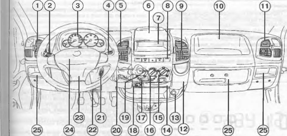
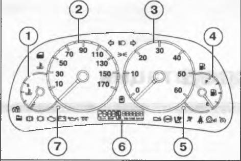 |
|
Рис. 1.3. Щиток приборов 1 — указатель температуры охлаждающей жидкости 2 — спи- дометр; 3 — -тахометр; 4 — указатель уровня топлива; 5 — кноп- ка установки счетчика пробега и напоминания о техническом обслуживании; 6 — дисплей; 7 кнопка установки часов. |
В нормальных условиях стрелка должна находиться в средней части шкалы.
Если она приближается к красному сектору, это означает, что двигатель перегружен и следует снизить нагрузку на него.
Движение с высокой скоростью при высокой температуре наружного воздуха также приводит к приближению стрелки к красному сектору. В таком случае рекомендуется остановиться и заглушить двигатель. Через некоторое время можно вновь запустить двигатель и слегка нажать на педаль акселератора.
Если ситуация не изменилась, заглушите двигатель и обратитесь на СТО для диагностики двигателя. Спидометр
Расположение спидометра (2) показано на рис. 1.3. Тахометр
Расположение тахометра (3) показано на рис 1.3.
Электронная система постепенно перекрывает подачу топлива во избежание превышения частотой вращения коленчатого вала двигателя пороговой величины. Указатель уровня топлива
Когда загорается сигнальная пампа низкого уровня топлива (см. 4. рис. 1.3), это означает, что в топливном баке остается приблизительно 8-10 л топлива.
Движение с почти пустым баком может привести к пропускам зажигания и повреждению каталитического нейтрализатора.
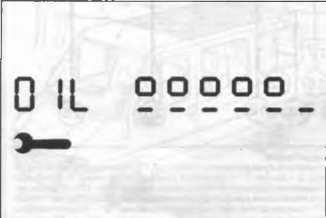 |
|
Рис. 1.4. Нормальный уровень моторного масла. |
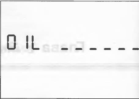 |
|
Рис. 1.5. Минимальный уровень моторного масла. |
Счетчик пробега
При нажатии кнопки (см. 5, рис. 1.3) на дисплее счетчика пробега последовательно отображаются общий и суточный пробег в км.
С помощью этой кнопки можно сбросить на 0 значение счетчика сугочного пробега, а также выбрать режим работы счетчика пробега (общий или суточный пробег):
— если отображаются показания счетчика общего пробега, нажмите кнопку менее чем на 2 сек., после отпускания кнопки будет отображаться счетчик суточного пробега,
— если отображаются показания счетчика суточного пробега, нажмите кнопку менее чем на 2 сек., после от-пускания кнопки будут отображаться показания счетчика общего пробега
— нажмите кнопку более чем на 2 сек. для сброса показаний счетчика суточного пробега.
Часы
Установку времени можно производить, даже когда двигатель не работает, а ключ извлечен из замка зажигания.
Установка времени
Показания часов изменяются на единицу при каждом нажатии и отпускании кнопки (см. 7, рис. 1.3).
При нажатии и удержании кнопки в нажатом положении происходит быстрая смена показаний часов.
Когда показания часов приближаются к требуемому значению, отпустите кнопку и завершите настройку вручную. Указатель уровня моторного масла
Указатель уровня моторного масла является дополнительным оборудованием и его наличие зависит от комплектации автомобиля.
Указатель в графическом формате отображает уровень моторного масла между метками «MIN» и «МАХ»
Для выполнения измерений установите автомобиль на ровную горизонтальную площадку, затем проделайте следующие операции:
— когда двигатель не работает, поверните ключ в замке зажигания в положение «MAR».
— на дисплее будет отображаться слово «OIL» (масло) в течение 5 сек. вместе с шестью отрезками и пятью или шестью квадратами, показывающими уровень моторного масла (см. рис. 1.4 и рис. 1.5).
Если уровень масла минимальный, в кратчайшие сроки доведите уровень масла до нормы. В любом случае, перед доливкой масла проконтролируйте его уровень с помощью маслоизмерительного щупа. Если на дисплее отображаются слова «ОIL HIGH» (рис. 1.6), это значит, что уровень выше максимально допустимого и необходимо снизить уровень масла.
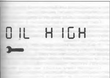 |
|
Рис. 1.6. Уровень моторного масла выше допустимого. |
При запуске двигателя во время выполнения измерения на индикаторе отобразится общий пробег или суточный пpoбеги время.
Нажмите и отпустите кнопку (см. 5, рис 1.3) для прекращения измерения; при этом на индикаторе отобразятся пробег и время. Индикатор технического обслуживания
Техническое обслуживание автомобиля должно про изводиться через каждые 15 ООО км пробега, но не реже одного раза в год.
Напоминание о необходимости очередного технического обслуживания (см. 1, рис. 1.7 и рис 1.8) отображается при поворачивании ключа в замке зажигания в положение «MAR» когда до очередного технического обслуживания остается 2 ООО км пробега или 30 дней и повторяется через каждые 200 км (см. 2 рис. 1.7) или один раз в три дня (см. 2 рис 1.8).
Примечание. Всегда соблюдайте сроки проведения тех- нического обслуживания, указанные в «Графике техничес- [ кого обслуживания» (см. ниже)
При каждом поворачивании ключ? р замке зажигания в положение «MAR» сигнальная лампа загорается приблизительно на 5 сек.
Индикатор технического обслуживания функционирует только когда двигатель не работает а ключ в замке зажигания находится в положении «MAR».
Когда ключ в замке зажигания находится в положении «МАR», отображается также символ индикатора технического обслуживания в виде гаечного ключа. Интервалы технического обслуживания
Индикатор настроен на 20 000 км или 1 год. График технического обслуживания может быть изменен в зависимости от условий эксплуатации и типа установленного двигателя (бензиновый или дизельный).
На дисплее отображаются следующие коды: CFG 1: 30 000 км и 365 дней для нормальных условий эксплуатации моделей с бензиновыми двигателями 2,0 и дизельными 2,0л JTD и 2,8л JTD и для тяжелых условий эксплуатации моделей с дизельным двигателем 2,3л JTD.
CFG 2: 20 000 км и 365 дней для тяжелых условий эксплуатации моделей с бензиновым двигателем 2,0л и дизельными двигателями 2,0л JTD и 2,8л JTD.
CFG 3:15 000 км и 365 дней для особо тяжелых условий эксплуатации модели с любыми типами двигателей. Процедура конфигурирования
Для изменения периодичности технического обслуживания на неподвижном автомобиле поверните ключ в замке зажигания в положение «MAR» и нажмите кнопку приблизительно на 10 сек.: на дисплее
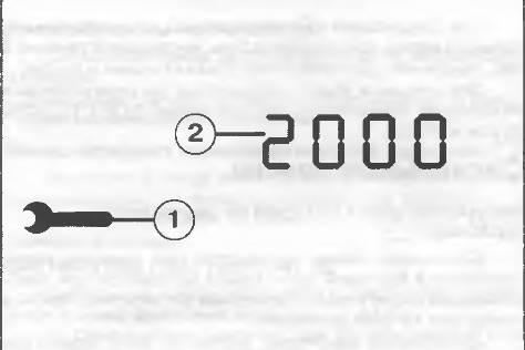 |
|
Рис. 1.7. Индикация оставшегося количества километ- ров пробега до следующего техобслуживания. |
отобразиться изображение гаечного ключа и надпись «CFG 1», «CFG 2» или «CFG 3». Нажмите и отпустите кнопку для выбора необходимой конфигурации, затем снова нажмите ее приблизительно на 5 сек., чтобы сохранить новые межсервисные интервалы; на дисплее вновь отобразятся показания часов и пробег в км. Пробег, оставшийся до следующего техническо- го обслуживания 2000 км
Когда до очередного технического обслуживания остается 2000 км пробега, при поворачивании ключа в замке зажигания в положение «МАЙ» отобразится индикатор технического обслуживания (см. 1, рис. 1.7 и рис. 1.8), после чего в течение 5 сек. будет отображаться оставшееся количество километров пробега (см. 2, рис. 1.7) или количество дней (см. 2, рис. 1.8), оставшихся до наступления срока очередного технического обслуживания.
Затем, через 5 сек. индикатор вернется в режим отображения счетчика пробега.
Сначала отображается информация о плановом техническом обслуживании. Обратитесь на СТО Fiat для проведения технического обслуживания и сброса индикатора.
При оставшемся нулевом пробеге
При повороте ключа в замке зажигания в положение «MAR» индикатор (см. 1, рис. 1.7 и рис. 1.8) загорится на 5 сек одновременно с индикацией пробега 0 км, оставшегося до очередного технического обслуживания.
Затем через 5 с индикатор (2) вернется в режим отображения показаний счетчика общего или суточного пробега.
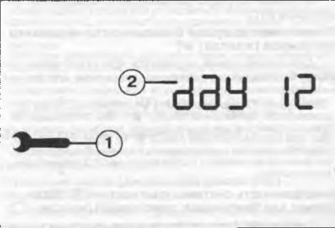 |
|
Рис. 1.8. Индикация оставшегося количества дней про- бега до следующего технического обслуживания. |
При следующем запуске появится как изображение гаечного ключа, так и пробег в 0 км, мигающие в течение 5 сек., после чего дисплей снова покажет время и пробег.
Эта ситуация будет повторяться до переустановки интервалов технического обслуживания («CFG 1», «CFG 2» или «CFG3»).
Сигнальные лампы
Аккумуляторная батарея не заряжается (красная) Q
Сигнальная лампа загорается при наличии неисправности в бортовой сети. Лампа загорается при поворачивании ключа в замке зажигания в положение «MAR» и гаснет при запуске двигателя.
Допускается некоторая задержка, если двигатель работает на оборотах холостого хода.
Обратитесь на СТО в кратчайшие сроки для предотвращения разряда аккумуляторной батареи. Аварийное давление масла в системе смазки двигателя (красная)
Сигнальная лампа загорается при снижении давления моторного масла ниже допустимого уровня.
Лампа загорается при поворачивании ключа в замке зажигания в положение «MAR» и гаснет при запуске дви гателя
Допускается некоторая задержка, если двигатель работает на оборотах холостого хода. Если двигатель сильно наг ружен то на оборотах холостого хода лампа может мигать.
Однако при легком нажатии на педаль акселератора она погаснет
Примечание. Если сигнальная лампа горит при движении автомобиля остановите двигатель и обратитесь на СТО.
Антипробуксовочная система (ASR) (желтая)
Сигнальная лампа загорается при поворачивании ключа в замке зажигания в положение «MAR» загорается сигнальная лампа, которая должна погаснуть через несколько секунд.
Сигнальная лампа мигает при движении автомобиля, чтобы предупредить водителя об активации антипробуксовочной системы.
При отключении системы с помощью специальной кнопки сигнальная лампа горит постоянно.
При включенной системе ASR и выявлении неисправности системы сигнальная лампа горит постоянно. Проверьте правильность этой информации, нажав на кнопку один раз (при этом, если система функционирует нормально, сигнальная лампа погаснет, в то время как при обнаружении неисправности, останется включенной).
В данной ситуации рекомендуется немедленно обратится на СТО.
Отключение подушки безопасности переднего пассажира (желтая)
Сигнальная лампа загорается при отключении подушки безопасности переднего пассажира кнопочным выключателем. Примечание. Сигнальная лампа обозначат также не- исправность сигнальной лампы Она отображается прерывистым миганием сигнальной лампы У дольше 4 сек. При этом сигнальная лампа не будет включаться, если обнаружится неиcnpaвнсть систем безопасности. Остановите автомобиль и обратитесь на СТО для диагнос- тики системы
Неисправность системы диагностики (EOBD) (только для бензиновых двигателей) (желтая)
Сигнальная лампа загорается при нормальном функционировании двигателя при поворачивании ключа в замке зажигания в положение «MAR» и должна погаснуть
после запуска двигателя. Включение сигнальной лампы свидетельствует о том, что она исправна.
Если сигнальная лампа загорается во время движения
Горит постоянно: предупреждение о неисправности системы пидачи топлива/зажигания, которая может привести к увеличению токсичности отработавших газов снижению мощности, ухудшению управляемости и увеличению расхода топлива.
В таких случаях можно продолжать движение, но не следует перегружать двигатель и двигаться с высокой скоростью. Продолжительная работа двигателя с горящей сигнальной лампой может в результате привести выходу его из строя. Немедленно обратитесь на СТО.
Сигнальная лампа погаснет, как только неисправность исчезнет. Однако код ошибки будет сохранен в мяти.
Мигает: предупреждение о возможности повреждения каталитического нейтрализатора
Если лампа мигает, необходимо плавно снизить обороты двигателя, пока лампа не перестанет мигать. должайте движение с невысокой скоростью.
Старайтесь избегать режимов работы двигателя, которых лампа снова начнет мигать. Обратитесь в кротчайшие сроки на СТО.
Неисправность системы подачи топлива (дизельные двигатели) (красная)
Сигнальная лампа загорается при возникновении неисправности в системе подачи топлива.
Сигнальная лампа должна загореться при повороте ключа зажигания в положение «MAR» и погаснуть через несколько секунд.
Сигнальная лампа загорается во время движения сигнализируя о неправильной работе системы под топлива, при этом возможно снижение мощности, управляемости и увеличение расхода топлива.
В таких случаях можно продолжать движение, следует не допускать большой нагрузки на двигатель на высоких скоростях. Необходимо в кратчайшие сроки обратиться на СТО
Длительное использование автомобиля с горящей сигнальной лампой может привести к повреждению двигателя.
Кратковременное включение контрольной лампы должно вызывать беспокойство. Высокая температура рабочей жидкости автоматической трансмиссии (красная)
При поворачивании ключа в замке зажигания в положение «MAR» загорится сигнальная лампа но она должна погаснуть через 4 сек. Если лампа мигает, это сигнализирует о неисправности в трансмиссии, если горит постоянно — о слишком высокой температуре рабочей жидкости в автоматической трансмиссии. Если сигнальная лампа:
Горит постоянно: слишком высокая температура рабочей жидкости автоматической трансмиссии
Сигнальная лампа мигает и горит постоянно во время движения, указывая, что температура рабочей жидкости достигла максимально допустимого значения; в таком случае необходимо остановить автомобиль, перевести рычаг селектора в положение «N» или «Р» и оставить двигатель работать на оборотах холостого хода (дождавшись включения вентиляторов системы охлаждения двигателя), пока сигнальная лампа не погаснет. После этого можно продолжать движение, избегая высоких нагрузок на двигатель.
При повторном включении сигнальной лампы остановите автомобиль, оставьте двигатель работать на оборотах холостого хода и дождитесь, пока сигнальная лампа погаснет
Если сигнальная лампа загорится вновь раньше чем через 15 мин остановите автомобиль, не глушите двигатель и дождитесь охлаждения двигателя и трансмиссии с помощью вентиляторов системы охлаждения.
Мигает: неисправность автоматической трансмиссии.
Сигнальная лампа, мигающая при запуске двигателя или во время движения, указывает на наличие неисправности автоматической трансмиссии.
Включите 3-ю передачу, и автоматическая система управления перейдет в аварийный режим работы.
При выключении и повторном включении двигателя система самотестирования может не допустить неисправность, и сигнальная лампа выключится.
Код неисправности будет сохранен в памяти, Вам необходимо обратиться на СТО для диагностики системы. Уровень охлаждающей жидкости (красная)
Эта сигнальная лампа является дополнительным оборудованием и ее наличие зависит от комплектации автомобиля.
Сигнальная лампа загорается, когда уровень охлаждающей жидкости в радиаторе опускается ниже минимально допустимого уровня.
Высокая температура охлаждающей жидкости (красная)
Сигнальная лампа загорается когда температура охлаждающей жидкости в системе охлаждения двигателя превышает максимально допустимую величину. Неисправность подушки безопасности (красная)
Эта сигнальная лампа является дополнительным оборудованием и ее наличие зависит от комплектации
автомобиля.
Сигнальная лампа загорается при неисправности в системе подушек безопасности.
Примечание. Если при поворачивании ключа в замке за- жигания в положение «МАR» сигнальная лампа не загора- ется или загорается при движении, это может указывать на наличие неисправности в системе безопасности; при этом подушки безопасности и аварийные натяжители ремней безопасности могут не активироваться при стол- кновении или сработать неожиданно. Немедленно оста- новите автомобиль и обратитесь на СТО для диагностики системы.
Рычаг стояночного тормоза взведен / н зкий уровень тормозной жидкости (красная)
Лампа может загораться в трех случаях:
— когда взведен рычаг стояночного тормоза;
Когда уровень тормозной жидкости опускается ниже минимально допустимого уровня;
— в сочетании с горящей сигнальной лампой системы распределения тормозных сил (EBD).
Примечание. Если во время движения загорается сиг- нальная лампа проверьте, взведен ли рычаг стояночного тормоза. Если сигнальная лампа загорается при опущен- ном рыча ; стояночного тормозе немедленно останови- те автомобиль и обратитесь на СТО.
Ремни безопасности(красная)
Сигнальная лампа загорается когда не пристегнут ремень безопасности водителя.
Двери открыты (красная)
Сигнальная лампа загорается, когда не закрыта одна из дверей.
Примечание. Сигнальная лампа устанавливается на неко- торых модификациях автомобилей.
Износ передних тормозных колодок (красная)
Загорается, когда износ накладок передних тормозных колодок достиг предельно допустимой величины.
Замените колодки и проверьте состояние задних тормозных колодок. Система Fiat code (желтая)
Сигнальная лампа загорается в следующих случаях (ключ в замке зажигания в положении «MAR»):
1. Однократное мигание при распознавании кода ключа. Разрешен запуск двигателя.
2. Горит постоянно — код ключа не распознан. Выполните процедуру аварийного пуска двигателя (см. «Устранение неисправностей»),
3. Мигает — автомобиль не защищен системой электронной блокировки запуска двигателя (Fiat code). Запуск двигателя возможен.
Слив воды из топливного фильтра (дизельные двигатели) (желтая)
Сигнальная лапа загорается при накоплении воды в топливном фильтре. Сигнальная лампа должна загореться при повороте ключа зажигания в положение «MAR» и погаснуть через несколько секунд. Примечание. Наличие воды в дизельном топливе может привести к серьезным повреждениям системы подачи топлива При включении сигнальной лампы необходимо срочно обратиться на СТО для диагностики системы. Сигнальная лампа, загоревшаяся сразу же после заправ- ки топливом, может свидетельствовать о наличии воды в топливном баке, в этом случае следует заглушить двига- тель и обратится на СТО.
Неисправность антиблокировочной системы (ABS) (желтый)
Сигнальная лампа загорается при возникновении неисправности антиблокировочной системы.
При этом обычная тормозная система продолжает функционировать без участия ABS, необходимо немедленно обратиться на СТО.
Сигнальная лампа должна загореться при поворачивании ключа в замке зажигания в положение «MAR» и погаснуть приблизительно через 2 сек.
Задние поотивотуманные фонари (желтая)
Сигнальная лампа загорается при включении задних противотуманных фонарей. Пусковые свечи (дизельный двигатель) (желтая)
Сигнальная лампа загорается при поворачивании ключа в замке зажигания в положение «MAR».
Лампа погаснет, когда пусковые свечи разогреются до требуемой температуры
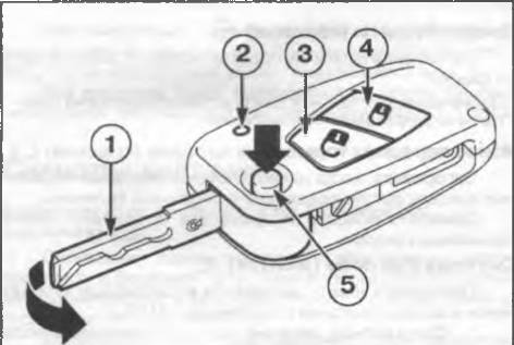 |
|
Рис. 1.9. Брелок дистанционного управления. |
Указатели поворота (проблесковый режим) (зеленая)
Загораются при включении указателей с помощью левого подрулевопэ переключателя. Круиз-контроль (зеленая)
Загорается при включении круиз-контроля (нажатой кнопке «ON»).
Внешние осветительные поиборы (зеленая)
Загорается при включении габаритных огней и ближнего света фар.
Дальний свет фар (синяя)
Загорается при включении дальнего света фар.
Система Fiat code
Для защиты от угона автомобиль оборудован элект ронной системой блокировки пуска двигателя (Fiat code), которая автоматически активизируется при извлечении ключа из замка зажигания.
В каждый ключ встроено электронное устройство, которое Формирует кодированный сигнал. При попытке запустить двигатель кодовый сигнал принимается антенной, встроенной в замок зажигания. Модулироранный сигнал который изменяется при каждом запуске двигателя, является паролем с помощью которого электронный блок управления распознает ключ и дает разрешение на запуск двигателя.
Ключи
В комплект поставки каждого автомобиля входят следующие ключи.
— два ключа без пульта дистанционного управления С помощью этого ключа возможны: запуск двигателя’ запирание/отпирание передних дверей; запирание/отпирание боковых сдвижных дверей; запирание/отпирание задних дверей, запирание/отпирание пробки заправочной горловины топливного бака.
— два ключа с пультом дистанционного управления Ключ с пультом дистанционного управления выполняет все вышеперечисленные функции, а также осуществляет дистанционное управление отпирание/запиранием дверей.
Примечание. Для обеспечения эффективного функциони- рования электронных компонентов необходимо избегать попадания на ключи прямых солнечных лучей.
— карточка Code так же, как и ключи, входит в комплект поставки автомобиля и содержит электронный код для аварийного запуска и код ключа, который необходимо сообщить сотрудникам СТО при заказе дубликатов ключей.
Охранная сигнализация
Охранная сигнализация может устанавливаться только на модели с закрепленной панелью и выполняет следующие функции:
— дистанционное запирание / отпирание дверей;
— контроль периметра, выявление открывания передни) дверей капота боковой и задней дверей’
контроль объема, только кабина; грузовое отделение не защищено.
Приемник охранной сигнализации, установленной на Fiat Ducato, расположен на переднем потолочном светальнике и принимает сигналы пульта дистанционного управления, работающего по радиоканалу.
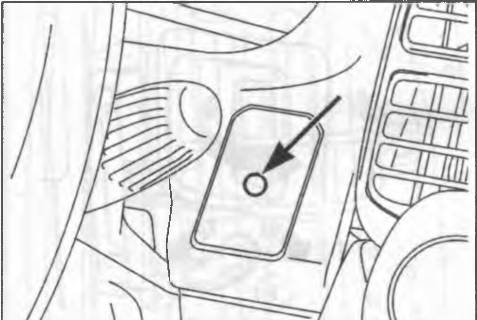 |
|
Рис. 1.12. Светодиод охранной сигнализации. |
Датчики объема (см. по стрелке, рис. 1.11) расположены на потолочном светильнике.
Охранная сигнализация может быть включена, только когда ключ извлечен из замка зажигания в положениях «STOP» или «PARK».
Электронный блок управления охранной сигнализации также включает сирену, которая может быть отключена. Включение охранной сигнализации
# Для включения охранной сигнализации: нажмите и отпустите кнопку пульта дистанционного управления (см. 4, рис. 1.9). Раздастся короткий звуковой сигнал, и приблизительно на 3 сек. загорятся указатели поворота.
Светодиод (см. по стрелке, рис. 1.12), расположенный справа от рулевой колонки, при включении охранной сигнализации активируется в проблесковом режиме. Выключение охранной сигнализации
Для отключения охранной сигнализации нажмите кнопку пульта дистанционного управления (см. 3, рис 1.9). Прозвучат два коротких звуковых сигнала, дваж ды мигнут указатели поворота.
Выключение / включение датчиков объема
Датчики объема можно отключить перед включением охранной сигнализации.
Быстро поверните ключ в замке зажигания из положения «STOP» в «MAR» а затем опять в положение «STOP».
Датчик объема будет включен вновь (перед включением охранной сигнализации) после поворота ключа в положение «MAR» на 30 сек.
Для работы с электрическими устройствами, функционирование которых зависит от положения ключа в замке зажигания (например, стеклоподъемниками), поверните ключ в положение «MAR», произведите необходимые операции с устройством и поверните ключ в положение «STOP» в течение 30 сек. При этом датчик объема не будет вновь активирован Выключение сирены
ф При включении охранной сигнализации удерживайте кнопку (см. 3, рис. 1.9) нажатой дольше 4 сек, после чего отпустите. Вы услошите пять звуковых сигналов, подтверждающих выключение сирены и включение охранной сигнализации.
Самодиагностика системы
Если при включенной охранной сигнализации после звукового сигнала включения раздается еще один звуко-
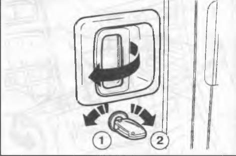 |
|
Рис. 1.13. Открывание , запирание дверей кабины вруч- ную снаружи. |
вой сигнал, проверьте, закрыты ли двери, капот и грузовой отсек Повторно включите охранную сигнализацию. Если ситуация не изменилась, обратитесь на СТО. Программирование системы
Охранная сигнализация была запрограммирована официальным дилером Fiat. Любое дальнейшее программирование должно производиться только на СТО Fiat. Причины срабатывания сигнализации
Охранная сигнализация может активироваться в следующих случаях открыты двери, капот и грузовой отсек;
— отсоединена аккумуляторная батарея или произошел обрыв питания охранной сигнализации
— зарегистрировано движение в кабине датчик объема);
— ключ зажигания повернут в положение «MAR».
При срабатывании сигнализации приблизительно на 26 сек. включается сирена (максимум 3 цикла с 5-секундными паузами если причина, вызвавшая срабатывание, не устранена) а указатели поворота мигают приблизительно в течение 5 мин.
При устранении причины срабатывания охранная сигнализация возвращается в режим охраны.
Чтобы выключить сигнализацию раньше, нажмите на кнопку пульта дистанционного управления- если это не удается, поверните аварийный ключ в положение «OFF». Отключение сигнализации
Если элемент питания пульта дистанционного управления разрядился или в случае возникновения неисправности охранная сигнализация может быть отключена с помощью одного из двух аварийных ключей блока де-
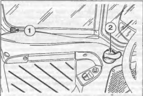 |
|
Рис. 1.14. Открывание / запирание дверей кабины вруч- ную изнутри. |
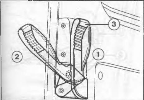 |
|
Рис. 1.16. Открывание / закрывание левой двойной за- дней двери. |
в Для запирания двери изнутри вручную закройте дверь
и нажмите кнопку фиксатора (1). Боковая сдвижная дверь
Примечание. При выводе из автомобиля с открытыми сдвижными дверями убедитесь, что двери надежно удер- живаются фиксаторами в открытом положении. Не допускается движение с открытой боковой дверью
Боковая сдвижная дверь открывается так же, как и дверь кабины, она снабжена фиксатором, удерживающим дверь в полностью открытом положении, в Потяните наружную дверную ручку (см. 1, рис. 1.15) (или соответствующую внутреннюю ручку) в направлении стрелки.
Выдвижная подножка
При открывании боковой двери из-под днища автомобиля выдвигается подножка, облегчающая выход из автомобиля.
Примечание. Перед выездом убедитесь, что подножка полностью выдвинута. Если подножка не полностью вы- винута или задние двери не закрыты, то на панели при- боров загорится сигнальная лампа
Двойные задние двери
Открывание / закрывание правой двери
Для открывания правой двери вручную снаружи поверните ключ в положение (см. 2, рис 1 13) и потяните рукоятку двери в направлении стрелки, Для закрывания правой двери вручную снаружи поверните ключ в положение (1). Для открывания правой задней двери вручную изнутри поднимите кнопку фиксатора и потяните ручку, Для закрывания правой двери вручную изнутри закройте дверь и нажмите кнопку фиксатора. Открывание / закрывание левой двери Для открывание левой двери вручную потяните руко-
ятку(см. 3, рис. 1.16) в положение (2). Для закрывания второй двери закройте дверь и нажмите рукоятку (3)
Двойные задние двери оснащены фиксатором, не допускающим открывание двери на угол больше 90 . Примечание. Убедитесь, что задняя левая дверь закрыта, а потом закрывайте правую дверь.
Открывание двойных задних дверей на угол 180
Для облегчения погрузочно-разгрузочных работ можно увеличить угла распахивания обеих дверей, Отсоедините тяги (см. 1, рис. 1.17). Это позволить открывать двери на угол приблизительно 180′.
При открывании на 180′ двери не фиксиру- ются. Не используйте эту систему, если автомобиль стоит на крутом уклоне или в ветреную погоду.
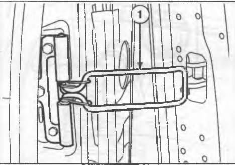 |
|
Рис 1.17. Фиксатор двойных задних дверей. |
Открывание двойных задних; ерей на угол 270°
Откроите и закроите дверь, как описано выше. Соедините тягу (1), фиксирующую дверь в открытом
состоянии на 90″. Полностью распахните двери в стороны. Двери оборудованы магнитными накладками (см. 1, рис. 1.18), удерживающими дверь в открытом положении Для закрывания дверей потяните дверь для преодоления силы действия магнитных накладок. Установите на место фиксирующую тягу и закройте дверь
Примечание. Недопустимо движение на автомобиле с от- крытыми задними дверями
Содержите в чистоте контактные поверхности л/ гнитных накладок, расположенных на двери и борту, чтобы сохра- нить эффективность их действия
Центральный замок
Центральная блокировка действуем для всех дверей при отпирании / запирании дверей кабины.
При функционировании блокировки одной из задних или боковых дверей только эта дверь будет заблокирована/разблокирована. Блокировка снаружи
Если двери закрыты, вставьте и поверните ключ в замок одной из дверей кабины, блокировка изнутри
Если двери закрыты, нажмите (чтобы заблокировать) или поднимите (чтобы разблокировать; одну из кнопок фиксатора дверей кабины.
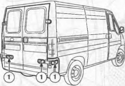 |
|
Рис. 1.18. Магнитные накладки дл полного открывания задних дверей. |
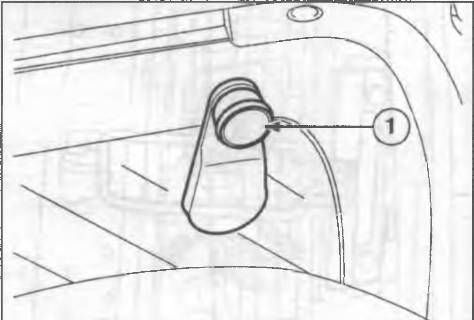 |
|
Рис. 1.19. Рукоятка управления стеклоподъемниками. |
Если одна из дверей кабины не закрыта или при сбое в системе функция центральной блокировки не будет функционировать, то после нескольких попыток устройство прекратит работу приблизительно на 2 мин. В течение этих двух минут можно заблокировать или разблокировать двери вручную, без участия центрального замка.
Через две минуты блок управления будет снова готов к получению команд. Если причина неправильной работы будет устранена, устройство вновь начнет работать правильно. Если нет, то снова будет отключено.
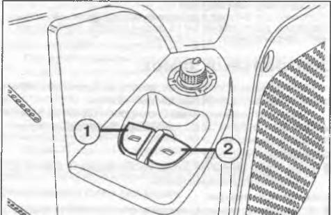 |
|
Рис. 1.20. Клавиши электрического управления стекло- подъемниками. |
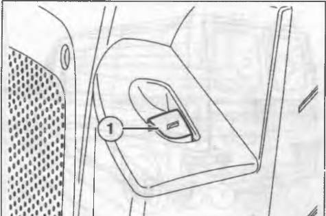 |
|
Рис. 1.21. Клавиша электрического управления стекло- подъемниками пассажирской двери. |
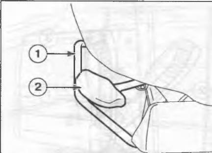 |
|
Рис. 1.22. Регулировка переднего сиденья. |
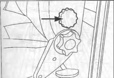 |
|
Рис. 1.24. Регулировка поясничном поддержки перед- него сиденья. |
Сиденья
Примечание. Регулировать сиденья рекомендуется толь- ко на стоящем автомобиле.
После регулировки сиденья проверьте надежность фик- сации сиденья. Ненадежная фиксация может привести к внезапному смещению сиденья.
Передние сиденья
Регулировка сиденья в горизонтальном направлении
Потяните вверх рычаг (см. 1, рис. 1 22) и переместите сиденье в горизонтальном направлении (вперед или назад’
Регулировка по высоте
Чтобы поднять сиденье. для регулировки передней части сиденья потяните вверх рычаг (2) или для регулировки задней части сиденья рычаг (см. 2, рис. 1.23) и перенесите вес тела с поднимаемой части сиденья, Чтобы опустить сиденье для регулировки передней части сиденья потяните вверх рычаг (см 2, рис. 1.22) или для регулировки задней части сиденья рычаг (см. 2, рис. 1.23) и перенесите вес тела на опускаемую часть сиденья. Регулировка угла наклона спинки сиденья
Вращайте рукоятку (см. 1. рис. 1.23). Регулировка поясничной поддержки
Регулировка поясничного подпора обеспечивает дополнительную поддержку поясничного отдела позвоночника, Для регулировки вращайте рукоятку (см. по стрелке, рис. 1.24).
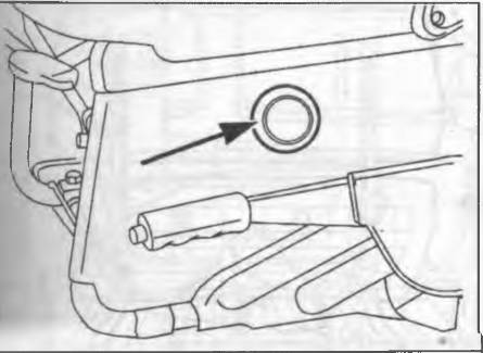 |
|
Рис. 1.25. Подогрев сиденья водителя. |
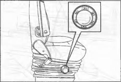 |
|
Рис. 1.26. Настройка сиденья под вес водителя. |
Подогрев сиденья водителя
Для включения подогрева сиденья нажмите кнопку (см. по стрелке, рис. 1.25), расположенную под сиденьем водителя (рядом с рычагом стояночного тормоза). Сиденье с амортизатором
Сиденье имеет механическую подвеску с пружинами и гидравлическими амортизаторами, обеспечивающую высочайший уровень комфорта и безопасность, система пружин позволяет поглощать воздействия, вызванные неровностями дорожного покрытия.
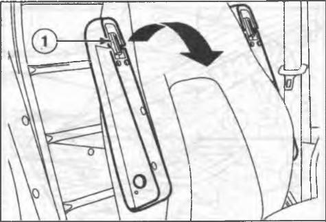 |
|
Рис. 1.27. Регулировка подлокотников. |
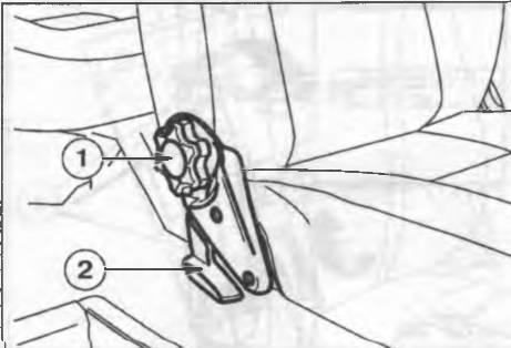 |
|
Рис. 1.28. Регулировка сидений модификации Panorama. _ |
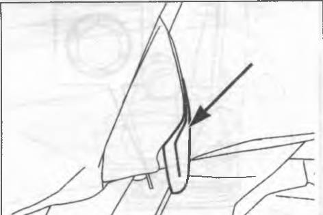 |
|
Рис. 1.29. Складывание центрального сиденья (2-3 ряды). |
Сиденье оснащено регулируемым по высоте подлокотником и подголовником.
Порядок деиствий для регулировки сиденья в продольном направлении по высоте, угла наклона сиденья и поясничной поддержки см. выше. Настоойка сиденья под вес водителя
С помощью рукоятки (см. рис 1.26) установите требуемый вес водителя в диапазоне от 40 до 130 кг Сиденья с регулируемыми подлокотниками
Сиденья водителя и пассажира могу- оснащаться двумя регулируемыми по высоте подлокотниками
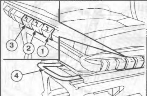 |
|
Рис. 1.30. Регулировка вращающегося сиденья. |
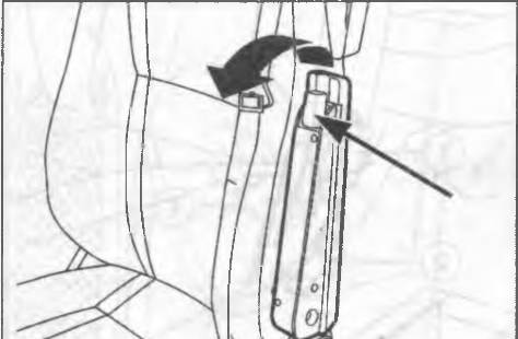 |
|
Рис. 1.31. Регулировка положения подлокотника вра- щающегося сиденья. |
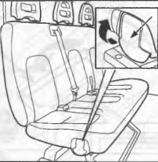
Рис. 1.34. Раскладывание сиденья (новая система крепления, третий ряд) — модификация Сотbi.
Регулировка угла наклона спинки сиденья
ф Нажмите кнопку (см. 1, рис. 1.30). Вращение сиденья
ф Для вращения сиденья полностью опустите переднюю
часть сиденья, ф Переместите сиденье назад до упора, ф Установите спинку сиденья вертикально, ф Нажмите кнопку (2) и поверните сиденье.
Из нормального рабочего положения сиденье можно повернуть на угол до 30′ в сторону двери (т.е. в наружную сторону) и на угол до 210′ вовнутрь автомобиля. Примечание. Когда автомобиле находится в движении, сиденья всегда должны быть зафиксированы в рабочем положении т. е. быть направлены строго вперед).
Регулировка по высоте
ф Нажмите кнопку (3) для поднимания/опускания сиденья.
Регулировка сиденья в горизонтальном направлении
ф Потяните рычаг (4) и переместите сиденье вперед или
назад.
Регулировка подлокотника
ф Отрегулируйте положение подлокотника с помощью регулировочного элемента (см. по стрелке, рис. 1.31,.
Модификация Combi
сскладывание сиденья (задний ряд)
Чтобы разложить сиденье заднего ряда, отстегните четыре пряжки ремней (см. 1 рис. 1.32) от сиденья,
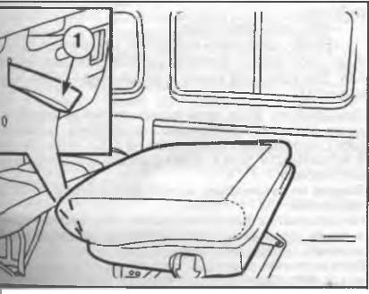 |
|
1.35. Раскладывание сиденья — новая система крепл. |
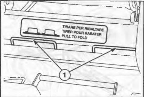 |
|
Рис. 1.36. Складывание сиденья — модификация Combi. |
поднимите два рычага (2) и сложите сиденье вперед (см. рис. 1.33).
Для раскладывания потяните сиденье назад и зафиксируйте стопорами. Убедитесь, что два рычага (2) находятся в горизонтальном положении и сиденье надежно зафиксировано, затем установите четыре пряжки ремней обратно на место.
Раскладывание сиденья (модификации с новой сис- темой крепления, 3-й ряд)
Примечание. Убедитесь, что спинка сиденья надежно за- креплена.
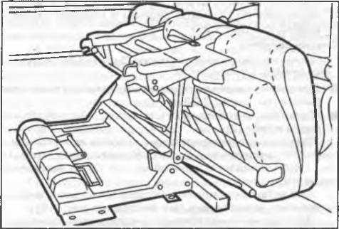 |
|
Рис. 1.37. Складывание сиденья — модификация Combi. |
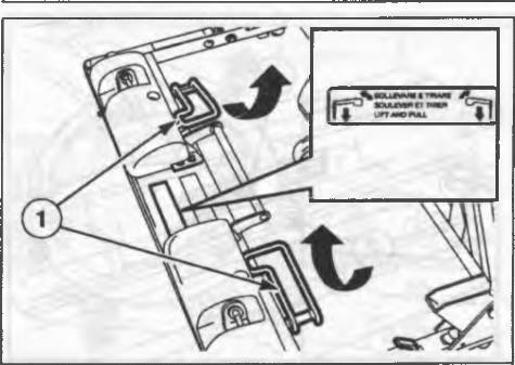 |
|
Рис. 1.38. Снятие сиденья — модификация Comb |
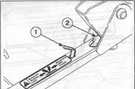 |
|
Рис. 1.39. Снятие сиденья — модификация Combi. |
Поднимите рычаг (см. по стрелке, рис. 1.34), чтобы наклонить спинку сиденья вперед.
Затем снимите подголовники, возьмитесь за петлю на задней части спинки (см. 1, рис. 1.35), слегка потяните спинку назад и полностью сложите ее вперед. Примечание. Не садитесь на сиденья третьего ряда со сложенной спинкой второго ряда сидений Не кладите предметы на сложенную спинку второго ряда сидений. Более подробная информация приведена на этикетке, расположенной под спинкой сиденья.
Складывание сиденья
Если после складывания спинки сиденье необходимо сложить, потяните за два рычага (см. 1, рис. 1.36), находящиеся под спинкой сиденья и сложите сиденье вперед (см. рис. 1.37).
Снятие сиденья Примечание. Сидение имеет массу 75 кг и его рекоменду- ется снимать с помощником.
Для снятия сиденья поднимите и затем вытяните два рычага (см. 1, рис. 1.38).
Убедитесь, что оба рычага (см. 1, рис. 1.39) опущены и виден штифт (2).
Сиденье отпущено правильным образом, когда красная метка на этикетке на подвижной части сиденья (см. 1, рис. 1.40) совпадает с зеленой меткой (2) на неподвижной части сиденья.
При установке сиденья убедитесь, что оно надежно закреплено, нажав педаль (см. по стрелке, рис. 1.41).
Зеленая метка на табличке на подвижной части сиденья (см. 1, рис. 1.40) должна совпадать с зеленой меткой (2) на неподвижной части сиденья.
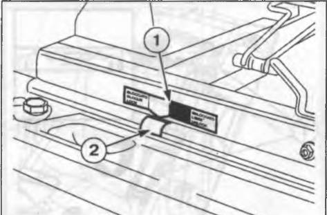 |
|
Рис. 1.40. Снятие сиденья — модификация Combi. |
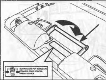 |
|
Рис. 1.41. Снятие сиденья — модификация Combi |
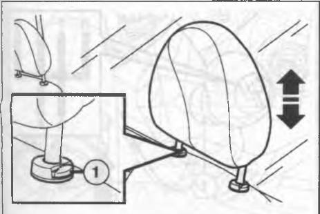 |
|
Рис. 1.42. Регулировка подголовников сидений. |
Рулевая колонка
Блокировка рулевой колонки
Для установки блокировки: извлеките ключ из замка зажигания, когда он находится в положении <STOP» или «PARK», и поверните рулевое колесо для блокировки. Для снятия блокировки: покачивая рулевое колесо из стороны в сторону, поверните ключ в замке зажигания в положение «MAR».
Примечание. Никогда не и; • пекайте ключ из з эмка зажи- чия во время движения. Это приведет к срабатыванию олокирующего ус -ройства рулевой колонкк., Это справед- ливо также и для буксируемого автомобиля. Запрещается вносить изменения в конструкцию рулевого управления (например устанавливать ополни ельные npow шонные устройства), поскольку это может повли- ять на безопасность движения.
регулировка угла наклона рулевой колонки
Положение рулевого колеса на всех модификациях может быть отрегулировано:
Переведите рычаг (см. 3, рис. 1 44) в положение (1). Отрегулируйте положение рулевого колеса. Возвратите рычаг в положение (2) для фиксации рулевой колонки.
Запуск бензинового двигателя
Примечание. Не нажимайте педаль акселератора перед запуском двигателя.
Проверьте, что рычаг стояночного тормоза взведен. Установите рычаг коробки переключения передач в
нейтральное положение. Полностью выжмите педаль сцепления, педаль акселератора не трогайте. Поверните ключ ч замке зажигания в положение «AW»
и отпустите его, как только двигатель запустится. Если двигатель не запустился с первой попытки, поверните ключ в замке зажигания обратно в положение «STOP» перед повторной попыткой запуска двы ателя. Если сигнальная лампа зS продолжает гореть, когда ключ в замке зажигания находится в положении «MAR», поверните ключ в положение «STOP», а затем снова в положение «MAR»; если сигнальная лампа все равно продолжает гореть, попробуйте использовать другие имеющиеся ключи. Если запустить двигатель все равно не удастся, обратитесь на СТО
Примечани э оставляйте ключ в замке зажигания в по- ложении «MaR», когда двигатель на работает.
аварийный запуск бензинового двигателя
Если система Fiat code не может отключить электронную блокировку двигателя, загорятся сигнальные лампы
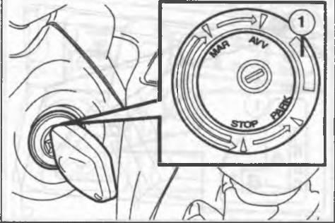 |
|
Рис. 1.43. Замок зажигания. |
и двигатель не запустится. В таком случае необходимо произвести аварийный пуск двигателя.
Тщательно ознакомьтесь с порядком проведения пооцедуры, прежде чем приступить к ее выполнению. Если в ходе операции была допущена ошибка, необходимо повернуть ключ в замке зажигания в положение «STOP» и повторить всю процедуру с шага 1.
1) Прочитайте 5-значный код, расположенный на карточке code.
2) Поверните ключ в замке зажигания в положение «MAR;
3) Нажмите и удерживайте педаль акселератора .Сигнальная лампа С: загорится примерно на 8 сек а затем погаснет. В этот момент отпустите педаль акселератора и приготовьтесь отсчитывать вспышки сигнальной лампы.
4) Отсчитайте количество вспышек, которое соответствует первой цифре кода карточки code, затем нажмите и удерживайте педаль акселератора пока сигнальная лампа о не загорится на 4 сек. и вновь не погаснет; после чего отпустите педаль акселератора.
5) Сигнальная лампа о вновь активируется в проблесковом режиме: после того, как количество вспышек сравняется со второй цифрой кода карточки code, нажмите медаль акселератора и удерживайте ее в нажатом положение.
6) Проделайте аналогичные операции для остальных цифр кода карточки code.
7) После того, как будет «введена» последняя цифра, удерживайте педаль акселератора в нажатом положении, сигнальная лампа загорится на 4 сек. и погаснет; после чего отпустите педаль акселератора.
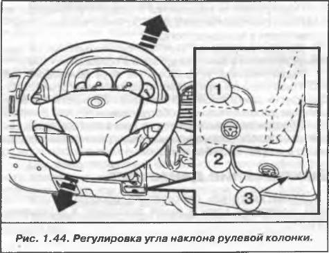
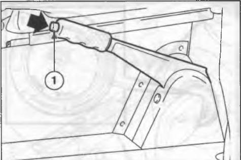 |
|
Рис. 1.45. Рычаг с тояночного тормоза. |
 Сигнальная лампа Сз будет часто мигать в течение примерно 4 сек , что указывает на то, что операция «ввода» кода была завершена правильно.
9) Запустите двигатель, повернув ключ в замке зажигания из положения «MAR» в положение «АЛА>.
Если сигнальная лампа продолжает гореть, поверните ключ в замке зажигания в положение «STOP» и повторите процедуру аварийного запуска с самого начал? Внимание П юле аварийного запуска необходимо обра- титься на СТО, иначе придется повторять вышеописанную процедуру при каждом запуске двигателя.
Запуск дизельного двигателя
Проверьте, что рычаг стояночного тормоза взведен. Установите рычаг коробки передач в нейтральное положение
Полностью выжмите педаль сцепления педаль акселератора не трогайте
Поверните ключ в замке зажигания в положение «MAR». На панели приборов загорятся сигнальные лампы
Дождитесь, пока сигнальная лампа на панели приборов погаснет.
Дождитесь, пока сигнальная лампа на панели приборов погаснет. Чем выше температура двигателя, тем быстрее погаснет лампа.
Поверните ключ в замке зажигания в положение сразу после тоге как лампа w погаснет.
Как только двигатель заработает, отпустите ключ. Примечание. Аварийный запуск дизельного двигателя не- возможен.
Подогреватель подаваемого воздуха (Heat Flang)
Подогреватель подаваемого воздуха установлен во впускной трубе двигателя 2,8л JTD для облегчения запуска двигателя в холодную погоду.
Данное устройство включается автоматически при повороте ключа в замке зажигания в положение «MAR».
Подогреватель установлен на всех двигателях 2,8 JTD с системой рециркуляции отработавших газов (EGR). Для других двигателей JTD он может быть установлен в качестве дополнительного оборудования.
Порядок действий при пуске двигателя одинаков как для двигателей, оборудованных подогревателем подаваемого воздуха, так и без него.
Выключение двигателя
Когда двигатель работает на оборотах холостого хода, поверните ключ в замке зажигания в положение «STOP».
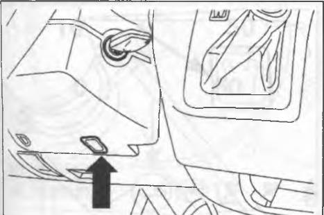 |
|
Рис. 1.47. Аварийное извлечение ключа из замка зажи- гания а тематическая трансмиссия. |
Автоматическая трансмиссия (двигатель 2,8л JTD)
На автомобилях Fiat Ducato установлена адаптирующаяся (способная приспосабливаться к стилю вождения водителя) автоматическая трансмиссия с четырьмя передачами для движения вперед и одной для движения назад. Трансмиссия обеспечивает непрерывную передачу мощности с очень быстрым переключением передач. Запуск двигателя
Двигатель может быть запущен, только когда рычаг селектора автоматической трансмиссии находится в положениях «Р» или «N»
По соображениям безопасности желательно запускать двигатель при нажатой педали тормоза. Примечание Начиная движение после запуска двигателе не нажимайте педаль акселератора перед, и во время пе- ремещения рычага селектора автоматической трансмис- сии Это особенно важно, когда двигатели не прогрет.
Начало движения
Запустив двигатель при оборотах холостого хода и нажатой педали тормоза, переместите рычаг селектора автоматической трансмиссии в позицию D. Отпустите педаль тормоза и плавно нажмите педаль акселератора.
Примечание Перемещение рычага селектора автомати- ческой трансмиссии из позиции «Р» возможно, только ко: да ключ в замке зажигания находится в положении «MAR», нажат кнопка рычага селектора и педаль тормоза.
Остановка автомобиля
Для остановки автомобиля просто нажмите на педаль тормоза, независимо от положения рычага селектора автоматической трансмиссии. Примечание. Ключ из замка зажигания извлекается толь- ко когда рычаг селектора автоматической трансмиссии наодится в положении «Р» в течение максимум 30 сек. с момента с тановки двигателя i >и открывании двери в течение приблизительно 15 сек. зуде; звучать звуковой сигнал (зуммер) для предупрежден чя водителя. В случае возникновения внештатной ситуации (неисправ- ность, разряженная батарея ит.д) ключ можно извлечь из замка, если в отверстие (см. рис. 1.47), расположенное под замком зажигания, вставить отвертку и нажать вверх. Автомобиль. стоящий на ровной поверхности, с работа- ющим на оборотах холостого хода двигателем и рычагом селектора автоматической трансмиссии, установленным в положения «D» или «R», может начать движение, если педаль тормоза не нажата.
Режимы переключения передач
Главная особенность описываемой автоматической трансмиссии заключается в возможности использования
![]()
Все ошибки Fiat 500, 500L, 500S, 500X, ALBEA, BRAVO, CROMA, DOBLO, FREEMONT, FULLBACK, GRANDE PUNTO, LINEA, PANDA, PANDA 4X4, PUNTO.
Ошибки Fiat по протоколу OBDI. Самодиагностика.
Ошибки Fiat по протоколу OBDII
Топливная система и воздухоподача
P0000-P0099, P0100-P0199, P0200-P0299
P0100 Неисправность цепи датчика расхода воздуха
P0101 Выход сигнала датчика расхода воздуха из допустимого диапазона
P0102 Низкий уровень выходного сигнала датчика расхода воздуха
P0103 Высокий уровень выходного сигнала датчика расхода воздуха
P0105 Неисправность датчика давления воздуха
P0106 Выход сигнала датчика давления воздуха из допустимого диапазона
P0107 Низкий уровень выходного сигнала датчика давления воздуха
P0108 Высокий уровень выходного сигнала датчика давления воздуха
P0110 Неисправность датчика температуры всасываемого воздуха
P0111 Выход сигнала датчика температуры всасываемого воздуха из допустимого диапазона
P0112 Низкий уровень датчика температуры всасываемого воздуха
P0113 Высокий уровень датчика температуры всасываемого воздуха
P0115 Неисправность датчика температуры охлаждающей жидкости
P0116 Выходсигнала датчика температуры охлаждающей жидкости из допустимого диапазона
P0117 Низкий уровень датчика температуры охлаждающей жидкости
P0118 Высокий уровень датчика температуры охлаждающей жидкости
P0120 Неисправность датчика положения дроссельной заслонки “A”
P0121 Выход сигнала датчика положения дроссельной заслонки “A” из допустимого диапазона
P0122 Низкий уровень выходного сигнала датчика положения дроссельной заслонки “A”
P0123 Высокий уровень выходного сигнала датчика положения дроссельной заслонки “A”
P0125 Низкая температура охлаждающей жидкости для управления по замкнутому контуру
P0130 Датчик кислорода 1 (банк 1) неисправен
P0131 Низкий уровень сигнала датчика кислорода 1 (банк 1)
P0132 Высокий уровень сигнала датчика кислорода 1 (банк 1)
P0133 Медленный отклик датчика кислорода 1 (банк 1) на обогащение/обеднение
P0134 Нет активности выходного сигнала датчика кислорода 1 (банк 1)
P0135 Нагреватель датчика кислорода 1 (банк 1) неисправен
P0136 Датчик кислорода 2 (банк 1) неисправен
P0137 Низкий уровень выходного сигнала датчика кислорода 2 (банк 1)
P0138 Высокий уровень выходного сигнала датчика кислорода 2 (банк 1)
P0139 Медленный отклик датчика кислорода 2 (банк 1) на обогащение/обеднение
P0140 Нет активности выходного сигнала датчика кислорода 2 (банк 1)
P0141 Нагреватель датчика кислорода 2 (банк 1) неисправен
P0142 Датчик кислорода 3 (банк 1) неисправен
P0143 Низкий уровень выходного сигнала датчика кислорода 3 (банк 1)
P0144 Высокий уровень выходного сигнала датчика кислорода 3 (банк 1)
P0145 Медленный отклик датчика кислорода 3 (банк 1) на обогащение/обеднение
P0146 Нет активности выходного сигнала датчика кислорода 3 (банк 1)
P0147 Нагреватель датчика кислорода 3 (банк 1) неисправен
P0150 Датчик кислорода 1 (банк 2) неисправен
P0151 Низкий уровень сигнала датчика кислорода 1 (банк 2)
P0152 Высокий уровень сигнала датчика кислорода 1 (банк 2)
P0153 Медленный отклик датчика кислорода 1 (банк 2) на обогащение/обеднение
P0154 Нет активности выходного сигнала датчика кислорода 1 (банк 2)
P0155 Нагреватель датчика кислорода 1 (банк 2) неисправен
P0156 Датчик кислорода 2 (банк 2) неисправен
P0157 Низкий уровень выходного сигнала датчика кислорода 2 (банк 2)
P0158 Высокий уровень выходного сигнала датчика кислорода 2 (банк 2)
P0159 Медленный отклик датчика кислорода 2 (банк 2) на обогащение/обеднение
P0160 Нет активности выходного сигнала датчика кислорода 2 (банк 2)
P0161 Нагреватель датчика кислорода 2 (банк 2) неисправен
P0162 Датчик кислорода 3 (банк 2) неисправен
P0163 Низкий уровень выходного сигнала датчика кислорода 3 (банк 2)
P0164 Высокий уровень выходного сигнала датчика кислорода 3 (банк 2)
P0165 Медленный отклик датчика кислорода 3 (банк 2) на обогащение/обеднение
P0166 Нет активности выходного сигнала датчика кислорода 3 (банк 2)
P0167 Нагреватель датчика кислорода 3 (банк 2) неисправен
P0171 Слишком бедная смесь (возможен подсос воздуха)
P0172 Слишком богатая смесь
P0173 Утечка топлива из топливной системы блока цилиндров №2
P0174 Смесь блока цилиндров №2 слишком бедная
P0175 Смесь блока цилиндров №2 слишком богатая
P0176 Датчик выброса СНх (Fuel Composition) неисправен
P0177 Сигнал датчика СНх (Fuel Composition) вне допустимого диапазона
P0178 Низкий уровень сигнала датчика СНх (Fuel Composition)
P0179 Высокий уровень сигнала датчика СНх (Fuel Composition)
P0180 Неисправность цепи датчика температуры топлива “А”
P0181 Сигнал датчика температуры топлива “А” вне допустимого диапазона
P0182 Низкий уровень сигнала датчика температуры топлива “А”
P0183 Высокий уровень сигнала датчика температуры топлива “А”
P0185 Неисправность цепи датчика температуры топлива “В”
P0186 Сигнал датчика температуры топлива “В” вне допустимого диапазона
P0187 Низкий уровень сигнала датчика температуры топлива “В”
P0188 Высокий уровень сигнала датчика температуры топлива “В”
P0190 Неисправность цепи датчика давления топлива в топливной рампе
P0191 Сигнал датчика давления в топливной рампе вне допустимого диапазона
P0192 Низкий сигнал датчика давления топлива в топливной рампе
P0193 Высокий сигнал датчика давления топлива в топливной рампе
P0194 Перемежающийся сигнал датчика давления топлива в топливной рампе
P0195 Неисправность цепи датчика температуры масла в двигателе
P0196 Сигнал датчика температуры масла в двигателе вне допустимого диапазона
P0197 Низкий сигнал датчика температуры масла в двигателе
P0198 Высокий сигнал датчика температуры масла в двигателе
P0199 Перемежающийся сигнал датчика температуры масла в двигателе
P0200 Неисправность цепи управления форсунками
P0201 Неисправность цепи управления форсункой №1
P0202 Неисправность цепи управления форсункой №2
P0203 Неисправность цепи управления форсункой №3
P0204 Неисправность цепи управления форсункой №4
P0205 Неисправность цепи управления форсункой №5
P0206 Неисправность цепи управления форсункой №6
P0207 Неисправность цепи управления форсункой №7
P0208 Неисправность цепи управления форсункой №8
P0209 Неисправность цепи управления форсункой №9
P0210 Неисправность цепи управления форсункой №10
P0211 Неисправность цепи управления форсункой №11
P0212 Неисправность цепи управления форсункой №12
P0213 Неисправность цепи управления форсункой холодного старта №1
P0214 Неисправность цепи управления форсункой холодного старта №2
P0215 Неисправность соленоида выключения двигателя
P0216 Неисправность цепи контроля времени впрыска
P0217 Перегрев двигателя
P0218 Перегрев трансмиссии
P0219 Двигатель “перекручен” (Engine Overspeed Condition)
P0220 Неисправность датчика положения дроссельной заслонки “B”
P0221 Сигнал датчика положения дроссельной заслонки “B” вне допустимого диапазона
P0222 Низкий уровень сигнала датчика положения дроссельной заслонки “B”
P0223 Высокий уровень сигнала датчика положения дроссельной заслонки “B”
P0224 Перемежающийся уровень сигнала датчика положения дроссельной заслонки “B”
P0225 Неисправность датчика положения дроссельной заслонки “C”
P0226 Сигнал датчика положения дроссельной заслонки вне допустимого диапазона “C”
P0227 Низкий уровень сигнала датчика положения дроссельной заслонки “C”
P0228 Высокий уровень сигнала датчика положения дроссельной заслонки “C”
P0229 Перемежающийся уровень сигнала датчика положения дроссельной заслонки “C”
P0230 Неисправность первичной цепи управления бензонасосом (упр. реле бензонасоса)
P0231 Постоянный низкий уровень вторичной цепи бензонасоса
P0232 Постоянный высокий уровень вторичной цепи бензонасоса
P0233 Перемежающийся уровень вторичной цепи бензонасоса
P0235 Неисправность цепи датчика давления турбонаддува “A”
P0236 Сигнал с датчика турбины “A” вне допустимого диапазона
P0237 Низкий уровень сигнала с датчика турбины “A”
P0238 Высокий уровень сигнала с датчика турбины “A”
P0239 Неисправность цепи датчика давления турбонаддува “B”
P0240 Сигнал с датчика турбины “B” вне допустимого диапазона
P0241 Низкий уровень сигнала с датчика турбины “B”
P0242 Высокий уровень сигнала с датчика турбины “B”
P0243 Неисправность соленоида затвора выхлопных газов турбины “A”
P0244 Сигнал соленоида затвора выхлопных газов турбины “A” вне доп. диапазона
P0245 Соленоид затвора выхлопных газов турбины “A” всегда открыт
P0246 Соленоид затвора выхлопных газов турбины “A” всегда закрыт
P0247 Неисправность соленоида затвора выхлопных газов турбины “B”
P0248 Сигнал соленоида затвора выхлопных газов турбины “B” вне доп. диапазона
P0249 Соленоид затвора выхлопных газов турбины “B” всегда открыт
P0250 Соленоид затвора выхлопных газов турбины “B” всегда закрыт
P0251 Неисправность насоса впрыска турбины”A”
P0252 Сигнал насоса впрыска турбины “A” не допустимого диапазона
P0253 Низкий уровень сигнала насоса впрыска турбины “A”
P0254 Высокий уровень сигнала насоса впрыска турбины “A”
P0255 Перемежающийся уровень сигнала насоса впрыска турбины “A”
P0256 Неисправность насоса впрыска турбины “B”
P0257 Сигнал насоса впрыска турбины “B” вне допустимого диапазона
P0258 Низкий уровень сигнала насоса впрыска турбины “B”
P0259 Высокий уровень сигнала насоса впрыска турбины “B”
P0260 Перемежающийся уровень сигнала насоса впрыска турбины “B”
P0261 Форсунка цилиндра №1 – замыкание на землю
P0262 Форсунка цилиндра №1 – обрыв или замыкание на +12V
P0263 Форсунка цилиндра №1 – неисправность драйвера форсунки
P0264 Форсунка цилиндра №2 – замыкание на землю
P0265 Форсунка цилиндра №2 – обрыв или замыкание на +12V
P0266 Форсунка цилиндра №2 – неисправность драйвера форсунки
P0267 Форсунка цилиндра №3 – замыкание на землю
P0268 Форсунка цилиндра №3 – обрыв или замыкание на +12V
P0269 Форсунка цилиндра №3 – неисправность драйвера форсунки
P0270 Форсунка цилиндра №4 – замыкание на землю
P0271 Форсунка цилиндра №4 – обрыв или замыкание на +12V
P0272 Форсунка цилиндра №4 – неисправность драйвера форсунки
P0273 Форсунка цилиндра №5 – замыкание на землю
P0274 Форсунка цилиндра №5 – обрыв или замыкание на +12V
P0275 Форсунка цилиндра №5 – неисправность драйвера форсунки
P0276 Форсунка цилиндра №6 – замыкание на землю
P0277 Форсунка цилиндра №6 – обрыв или замыкание на +12V
P0278 Форсунка цилиндра №6 – неисправность драйвера форсунки
P0279 Форсунка цилиндра №7 – замыкание на землю
P0280 Форсунка цилиндра №7 – обрыв или замыкание на +12V
P0281 Форсунка цилиндра №7 – неисправность драйвера форсунки
P0282 Форсунка цилиндра №8 – замыкание на землю
P0283 Форсунка цилиндра №8 – обрыв или замыкание на +12V
P0284 Форсунка цилиндра №8 – неисправность драйвера форсунки
P0285 Форсунка цилиндра №9 – замыкание на землю
P0286 Форсунка цилиндра №9 – обрыв или замыкание на +12V
P0287 Форсунка цилиндра №9 – неисправность драйвера форсунки
P0288 Форсунка цилиндра №10 – замыкание на землю
P0289 Форсунка цилиндра №10 – обрыв или замыкание на +12V
P0290 Форсунка цилиндра №10 – неисправность драйвера форсунки
P0291 Форсунка цилиндра №11 – замыкание на землю
P0292 Форсунка цилиндра №11 – обрыв или замыкание на +12
P0293 Форсунка цилиндра №11 – неисправность драйвера форсунки
P0294 Форсунка цилиндра №12 – замыкание на землю
P0295 Форсунка цилиндра №12 – обрыв или замыкание на +12V
P0296 Форсунка цилиндра №12 – неисправность драйвера форсунки
Система зажигания
P0300-P0399
P0300 Обнаружены случайные/множественные пропуски зажигания
P0301 Обнаружены пропуски зажигания в цилиндре №1
P0302 Обнаружены пропуски зажигания в цилиндре №2
P0303 Обнаружены пропуски зажигания в цилиндре №3
P0304 Обнаружены пропуски зажигания в цилиндре №4
P0305 Обнаружены пропуски зажигания в цилиндре №5
P0306 Обнаружены пропуски зажигания в цилиндре №6
P0307 Обнаружены пропуски зажигания в цилиндре №7
P0308 Обнаружены пропуски зажигания в цилиндре №8
P0309 Обнаружены пропуски зажигания в цилиндре №9
P0310 Обнаружены пропуски зажигания в цилиндре №10
P0311 Обнаружены пропуски зажигания в цилиндре №11
P0312 Обнаружены пропуски зажигания в цилиндре №12
P0320 Неисправноcть цепи распределителя зажигания
P0321 Сигнал распределителя зажигания вне допустимого диапазона
P0322 Сигнал распределителя зажигания отсутствует
P0323 Сигнал распределителя зажигания перемежающийся
P0325 Неисправность цепи датчика детонации №1
P0326 Сигнал датчика детонации №1 вне допустимого диапазона
P0327 Низкий уровень сигнала датчика детонации №1
P0328 Высокий уровень сигнала датчика детонации №1
P0329 Перемежающийся уровень сигнала датчика детонации №1
P0330 Неисправность цепи датчика детонации №2
P0331 Сигнал датчика детонации №2 вне допустимого диапазона
P0332 Низкий уровень сигнала датчика детонации №2
P0333 Высокий уровень сигнала датчика детонации №2
P0334 Перемежающийся уровень сигнала датчика детонации №2
P0335 Ошибка датчика положения коленвала”A”
P0336 Ошибка ДПКВ “A” (пропуск одного зуба)
P0337 Низкий уровень или замыкание на массу ДПКВ “A”
P0338 Высокий уровень или замыкание на +12V ДПКВ “A”
P0339 Перемежающийся сигнал ДПКВ “A”
P0340 Неисправность датчика распределительного вала
P0341 Сигнал датчика распределительного вала вне допустимого диапазона
P0342 Низкий уровень сигнала датчика распределительного вала
P0343 Высокий уровень сигнала датчика распределительного вала
P0344 Перемежающийся уровень сигнала датчика распределительного вала
P0350 Неисправность первичной / вторичной цепи катушки зажигания
P0351 Неисправность первичной / вторичной цепи катушки зажигания “A”
P0352 Неисправность первичной / вторичной цепи катушки зажигания “B”
P0353 Неисправность первичной / вторичной цепи катушки зажигания “C”
P0354 Неисправность первичной / вторичной цепи катушки зажигания “D”
P0355 Неисправность первичной / вторичной цепи катушки зажигания “E”
P0356 Неисправность первичной / вторичной цепи катушки зажигания” F”
P0357 Неисправность первичной / вторичной цепи катушки зажигания “G”
P0358 Неисправность первичной / вторичной цепи катушки зажигания “H”
P0359 Неисправность первичной / вторичной цепи катушки зажигания “I”
P0360 Неисправность первичной / вторичной цепи катушки зажигания “J”
P0361 Неисправность первичной / вторичной цепи катушки зажигания “K”
P0362 Неисправность первичной / вторичной цепи катушки зажигания “L”
P0370 TIMING REF (HRS) A MAILFUNCTION
P0371 TIMING REF (HRS) A TOO MANY PULSES
P0372 TIMING REF (HRS) A TOO MANY PULSES
P0373 TIMING REF (HRS) A INTERMITTENT PULSES
P0374 TIMING REF (HRS) A NO PULSES
P0375 TIMING REF (HRS) B MAILFUNCTION
P0376 TIMING REF (HRS) B TOO MANY PULSES
P0377 TIMING REF (HRS) B TOO MANY PULSES
P0378 TIMING REF (HRS) B INTERMITTENT PULSES
P0379 TIMING REF (HRS) B NO PULSES
P0380 Неисправность свечи накаливания или цепи нагрева
P0381 Неисправность свечи накаливания или индикатора нагрева
P0385 Неисправность цепи датчика положения коленвала “B”
P0386 Сигнал датчика положения коленвала “B” вне допустимого диапазона
P0387 Низкий уровень или замыкание на массу ДПКВ “В”
P0388 Высокий уровень или замыкаение на +12V ДПКВ “В”
P0389 Перемежающийся сигнал датчика положения коленвала “B”
Контроль выбросов
P0400-P0499
P0400 Неисправность системы рециркуляции отработанных газов
P0401 Неэффективность системы рециркуляции отработанных газов
P0402 Избыточность системы рециркуляции отработанных газов (ОГ)
P0403 Неисправность цепи датчика системы рециркуляции отработанных газов
P0404 Сигнал датчика системы рециркуляции ОГ вне допустимого диапазона
P0405 Низкий уровень сигнала датчика “A” системы рециркуляции ОГ
P0406 Высокий уровень сигнала датчика “A” системы рециркуляции ОГ
P0407 Низкий уровень сигнала датчика “В” системы рециркуляции ОГ
P0408 Высокий уровень сигнала датчика “В” системы рециркуляции ОГ
P0410 Неисправность системы вторичной подачи воздуха
P0411 Некорректный поток через систему вторичной подачи воздуха
P0412 Неисправность клапана системы вторичной подачи воздуха”A”
P0413 Клапан системы вторичной подачи воздуха “A” всегда открыт
P0414 Клапан системы вторичной подачи воздуха “A” всегда закрыт
P0415 Неисправность клапана системы вторичной подачи воздуха “В”
P0416 Клапан системы вторичной подачи воздуха “В” всегда открыт
P0417 Клапан системы вторичной подачи воздуха “В” всегда закрыт
P0420 Эффективность системы катализаторов В1 ниже допустимого порога
P0421 Эффективность прогрева катализаторов В1 ниже допустимого порога
P0422 Эффективность главного катализатора В1 ниже допустимого порога
P0423 Эффективность нагревателя катализатора В1 ниже допустимого порога
P0424 Температура нагревателя катализатора В1 ниже допустимого порога
P0430 Эффективность системы катализаторов В2 ниже допустимого порога
P0431 Эффективность прогрева катализаторов В3 ниже допустимого порога
P0432 Эффективность главного катализатора В2 ниже допустимого порога
P0433 Эффективность нагревателя катализатора В2 ниже допустимого порога
P0434 Температура нагревателя катализатора В2 ниже допустимого порога
P0440 Неисправность контроля системы улавливания паров бензина
P0441 Плохая продувка системы улавливания паров бензина
P0442 Небольшая утечка в системе улавливания паров бензина
P0443 Неисправность цепи клапана продувки системы улавливания паров бензина
P0444 Клапан продувки системы улавливания паров бензина всегда открыт
P0445 Клапан продувки системы улавливания паров бензина всегда закрыт
P0446 Неисправность упр. воздушным клапаном системы улавливания паров
P0447 Воздушный клапан системы улавливания паров всегда открыт
P0448 Воздушный клапан системы улавливания паров всегда закрыт
P0450 Неисправность датчика давления паров бензина
P0451 Сигнал датчика давления паров бензина вне допустимого диапазона
P0452 Низкий уровень сигнал датчика давления паров бензина
P0453 Высокий уровень сигнал датчика давления паров бензина
P0454 Перемежающийся уровень сигнал датчика давления паров бензина
P0455 Большая утечка в системе улавливания паров бензина
P0460 Неисправность цепи датчика уровня топлива
P0461 Сигнал датчика уровня топлива вне допустимого диапазона
P0462 Низкий уровень сигнала датчика уровня топлива
P0463 Высокий уровень сигнала датчика уровня топлива
P0464 Перемежающийся уровень сигнала датчика уровня топлива
P0465 Неисправность цепи датчика потока воздуха продувки
P0466 Сигнал датчика потока воздуха продувки вне допустимого диапазона
P0467 Низкий уровень сигнала датчика потока воздуха продувки
P0468 Высокий уровень сигнала датчика потока воздуха продувки
P0469 Перемежающийся уровень сигнала датчика потока воздуха продувки
P0470 Неисправность датчика давления выхлопных газов
P0471 Сигнал датчика давления выхлопных газов вне допустимого диапазона
P0472 Низкий уровень сигнала датчика давления выхлопных газов
P0473 Высокий уровень сигнала датчика давления выхлопных газов
P0474 Перемежающийся уровень сигнала датчика давления выхлопных газов
P0475 Неисправность клапана датчика давления выхлопных газов
P0476 Сигнал клапана датчика давления выхлопных газов вне допустимого диапазона
P0477 Низкий уровень сигнала клапана датчика давления выхлопных газов
P0478 Высокий уровень сигнала клапана датчика давления выхлопных газов
P0479 Перемежающийся уровень сигнала клапана датчика давления выхлопных газов
P0480 Неисправность цепи управления реле вентилятора
Контроль скорости и холостого хода
P0500-P0599
P0500 Нет сигнала датчика скорости автомобиля
P0501 Сигнал датчика скорости автомобиля вне допустимого диапазона
P0502 Низкий уровень сигнала датчика скорости автомобиля
P0503 Высокий уровень сигнала датчика скорости автомобиля
P0505 Неисправность регулятора холостого хода
P0506 Неисправность регулятора холостого хода – низкие обороты
P0507 Неисправность регулятора холостого хода – высокие обороты
P0510 Closed Throttle Position Switch Malfunction
P0520 Engine Oil Pressure Sensor/Switch Circuit Malfunction
P0521 Engine Oil Pressure Sensor/Switch Circuit Range/Performance
P0522 Engine Oil Pressure Sensor/Switch Circuit Low Voltage
P0523 Engine Oil Pressure Sensor/Switch Circuit High Voltage
P0530 A/C Refrigerant Pressure Sensor Circuit Malfunction
P0531 A/C Refrigerant Pressure Sensor Circuit Range/Performance
P0532 A/C Refrigerant Pressure Sensor Circuit Low Input
P0533 A/C Refrigerant Pressure Sensor Circuit High Input
P0534 Air Conditioner Refrigerant Charge Loss
P0550 Power Steering Pressure Sensor Circuit Malfunction
P0551 Power Steering Pressure Sensor Circuit Range/Performance
P0552 Power Steering Pressure Sensor Circuit Low Input
P0553 Power Steering Pressure Sensor Circuit High Input
P0554 Power Steering Pressure Sensor Circuit Intermittent
P0560 Напряжение питания системы ниже порога работоспособности
P0561 Напряжение питания системы нестабильное
P0562 Низкое напряжение питания системы
P0563 Высокое напряжение питания системы
P0565 Неисправность сигнала включения круиз-контроля
P0566 Неисправность сигнала выключения круиз-контроля
P0567 Cruise Control Resume Signal Malfunction
P0568 Cruise Control Set Signal Malfunction
P0569 Cruise Control Coast Signal Malfunction
P0570 Cruise Control Accel Signal Malfunction
P0571 Cruise Control/Brake Switch A Circuit Malfunction
P0572 Cruise Control/Brake Switch A Circuit Low
P0573 Cruise Control/Brake Switch A Circuit High
P0574 Cruise Control Related Malfunction
P0575 Cruise Control Related Malfunction
P0576 Cruise Control Related Malfunction
P0577 Cruise Control Related Malfunction
P0578 Cruise Control Related Malfunction
P0579 Cruise Control Related Malfunction
P0580 Cruise Control Related Malfunction
Электронный блок управления (ЭБУ) и его подсистемы
P0600-P0699
P0600 Serial Communication Link Malfunction
P0601 Ошибка контрольной суммы ПЗУ
P0602 Control Module Programming Error
P0603 Ошибка внешнего ОЗУ
P0604 Ошибка внутреннего ОЗУ
P0605 Internal Control Module Read Only Memory (ROM) Error
P0606 PCM Processor Fault
P0607 Неисправность канала детонации
P0608 Control Module VSS Output “A” Malfunction
P0609 Control Module VSS Output “B” Malfunction
P0620 Generator Control Circuit Malfunction
P0621 Generator Lamp “L” Control Circuit Malfunction
P0622 Generator Field “F” Control Circuit Malfunction
P0650 Malfunction Indicator Lamp (MIL) Control Circuit Malfunction
P0654 Engine RPM Output Circuit Malfunction
P0655 Engine Hot Lamp Output Control Circuit Malfucntion
P0656 Fuel Level Output Circuit Malfunction
Трансмиссия
P0700-P0799, P0800-P0899, P0900-P0999
P0700 Неисправность системы контроля трансмиссии
P0701 Система контроля трансмиссии вне допустимого диапазона
P0702 Transmission Control System Electrical
P0703 Torque Converter/Brake Switch B Circuit Malfunction
P0704 Clutch Switch Input Circuit Malfunction
P0705 Transmission Range Sensor Circuit malfunction (PRNDL Input)
P0706 Transmission Range Sensor Circuit Range/Performance
P0707 Transmission Range Sensor Circuit Low Input
P0708 Transmission Range Sensor Circuit High Input
P0709 Transmission Range Sensor Circuit Intermittent
P0710 Transmission Fluid Temperature Sensor Circuit Malfunction
P0711 Transmission Fluid Temperature Sensor Circuit Range/Performance
P0712 Transmission Fluid Temperature Sensor Circuit Low Input
P0713 Transmission Fluid Temperature Sensor Circuit High Input
P0714 Transmission Fluid Temperature Sensor Circuit Intermittent
P0715 Input/Turbine Speed Sensor Circuit Malfunction
P0716 Input/Turbine Speed Sensor Circuit Range/Performance
P0717 Input/Turbine Speed Sensor Circuit No Signal
P0718 Input/Turbine Speed Sensor Circuit Intermittent
P0719 Torque Converter/Brake Switch B Circuit Low
P0720 Output Speed Sensor Circuit Malfunction
P0721 Output Speed Sensor Range/Performance
P0722 Output Speed Sensor No Signal
P0723 Output Speed Sensor Intermittent
P0724 Torque Converter/Brake Switch B Circuit High
P0725 Engine Speed input Circuit Malfunction
P0726 Engine Speed Input Circuit Range/Performance
P0727 Engine Speed Input Circuit No Signal
P0728 Engine Speed Input Circuit Intermittent
P0730 Incorrect Gear Ratio
P0731 Gear 1 Incorrect ratio
P0732 Gear 2 Incorrect ratio
P0733 Gear 3 Incorrect ratio
P0734 Gear 4 Incorrect ratio
P0735 Gear 5 Incorrect ratio
P0736 Reverse incorrect gear ratio
P0740 Torque Converter Clutch Circuit Malfuction
P0741 Torque Converter Clutch Circuit Performance or Stuck Off
P0742 Torque Converter Clutch Circuit Stuck On
P0743 Torque Converter Clutch Circuit Electrical
P0744 Torque Converter Clutch Circuit Intermittent
P0745 Pressure Control Solenoid Malfunction
P0746 Pressure Control Solenoid Performance or Stuck Off
P0747 Pressure Control Solenoid Stuck On
P0748 Pressure Control Solenoid Electrical
P0749 Pressure Control Solenoid Intermittent
P0750 Shift Solenoid A MalfunctionP
P0751 Shift Solenoid A PerformanceP or Stuck Off
P0752 Shift Solenoid A Stuck On
P0753 Shift Solenoid A ElectricaPl
P0754 Shift Solenoid A IntermittPent
P0755 Shift Solenoid B Malfunction
P0756 Shift Solenoid B Performance or Stuck Off
P0757 Shift Solenoid B Stuck On
P0758 Shift Solenoid B Electrical
P0759 Shift Solenoid B Intermittent
P0760 Shift Solenoid C Malfunction
P0761 Shift Solenoid C Performance or Stuck Off
P0762 Shift Solenoid C Stuck On
P0763 Shift Solenoid C Electrical
P0764 Shift Solenoid C Intermittent
P0765 Shift Solenoid D Malfunction
P0766 Shift Solenoid D Performance or Stuck Off
P0767 Shift Solenoid D Stuck On
P0768 Shift Solenoid D Electrical
P0769 Shift Solenoid D Intermittent
P0770 Shift Solenoid E Malfunction
P0771 Shift Solenoid E Performance or Stuck Off
P0772 Shift Solenoid E Stuck On
P0773 Shift Solenoid E Electrical
P0774 Shift Solenoid E Intermittent
P0780 Shift Malfunction
P0781 1-2 Shift Malfunction
P0782 2-3 Shift Malfunction
P0783 3-4 Shift Malfunction
P0784 4-5 Shift Malfunction
P0785 Shift/Timing Solenoid Malfunction
P0786 Shift/Timing Solenoid Range/Performance
P0787 Shift/Timing Solenoid Low
P0788 Shift/Timing Solenoid High
P0789 Shift/Timing Solenoid Intermittent
P0790 Normal/Performance Switch Circuit Malfunction
P0801 Reverse Inhibit Control Circuit Malfunction
P0803 1-4 Upshift (Skip Shift) Solenoid Control Circuit Malfunction
P0804 1-4 Upshift (Skip Shift) Lamp Control Circuit Malfunction
Прочие ошибки
P1000 OBD II Monitor Testing not complete
P1001 Key On Engine Running (KOER) Self-Test not able to complete. KOER aborted
P1100 Mass Air Flow (MAF) sensor intermittent
P1101 Mass Air Flow (MAF) sensor out of Self-Test range
P1102 Низкое сопротивление подогревателя датчика кислорода
P1110 Switch over valve solenoid
P1112 Switch over valve 1
P1113 Switch over valve 2
P1116 О2 Sensor heater Circuit (Open)
Engine Coolant Temperature (ECT) sensor out of Self – Test range
P1117 Engine Coolant Temperature (ECT) sensor intermittent
P1120 Throttle Position (TP) sensor out of range low
P1121 Throttle Position (TP) sensor inconsistent with MAF Sensor
P1123 Long Term Fuel Trim Additive Air (System too Rich)
P1124 Throttle Position (TP) sensor out of Self -Test range
Long Term Fuel Trim Additive Air (System too Lean)
P1125 Throttle Position (TP) sensor circuit intermittent
P1127 Exhaust not warm enough, downstream Heated Oxygen Sensors (HO2Ss) not tested
Long Term Fuel Trim Multiplicative (System too Rich)
P1128 Upstream Heated Oxygen Sensors (HO2Ss) swapped from bank to bank
Long Term Fuel Trim Multiplicative (System too Lean)
P1129 Downstream Heated Oxygen Sensors (HO2Ss) swapped from bank to bank
P1130 Lack of upstream Heated Oxygen Sensor (HO2S 11) switch, adaptive fuel at limit (Bank # 1)
P1131 Lack of upstream Heated Oxygen Sensor (HO2S 11) switch, sensor indicates lean (Bank # 1))
P1132 Lack of upstream Heated Oxygen Sensor (HO2S 11) switch, sensor indicates rich (Bank # 1)
P1136 Long Term Fuel Trim Additive Fuel (System too Rich)
P1137 Lack of downstream Heated Oxygen Sensor (HO2S 12) switch, sensor indicates lean (Bank # 1)
Long Term Fuel Trim Additive Fuel (System too Lean)
P1138 Lack of downstream Heated Oxygen Sensor (HO2S 12) switch, sensor indicates rich (Bank # 1)
P1140 Неверный сигнал нагрузки
P1150 Lack of upstream Heated Oxygen Sensor (HO2S 21) switch, adaptive fuel at limit (Bank #2)
P1151 Lack of upstream Heated Oxygen Sensor (HO2S 21) switch, sensor indicates lean (Bank # 2)
P1152 Lack of upstream Heated Oxygen Sensor (HO2S 21) switch, sensor indicates rich (Bank # 2)
P1157 Lack of downstream Heated Oxygen Sensor (HO2S 22) switch, sensor indicates lean (Bank # 2)
P1158 Lack of downstream Heated Oxygen Sensor (HO2S 22) switch, sensor indicates rich (Bank # 2)
P1171 Низкий уровень сигнала СО-потенциометра
P1172 Высокий уровень сигнала СО-потенциометра
P1174 02 Sensor 1 Bank 1 (period monitoring)
P1176 02 Sensor 1 Bank 1 (tv monitoring)
P1220 Series Throttle Control system malfunction
P1224 Throttle Position Sensor B (TP-B) out of Self – Test range
P1229 Power Supply Relay Primary Circuit Voltage High
P1230 Power Supply Relay Secondary Circuit Voltage Low
P1231 Fuel pump relay circuit low with high speed pump on
P1232 Low speed Fuel Pump primary circuit malfunction
P1233 Fuel Pump Driver Module disabled or offline
P1234 Fuel Pump Driver Module disabled or offline
P1235 Fuel Pump control out of Self – Test range
P1236 Fuel Pump control out of Self – Test range
P1237 Fuel Pump secondary circuit malfunction
P1238 Fuel Pump secondary circuit malfunction
P1260 THEFT detected – engine disabled
P1270 Engine RPM or vehicle speed limiter reached
P1285 Cylinder Head over temperature sensed
P1288 Cylinder Head Temperature (CHT) sensor out of Self – Test range
P1289 Cylinder Head Temperature (CHT) sensor circuit low input
P1290 Cylinder Head Temperature (CHT) sensor circuit high input
P1299 Engine over temperature condition
P1326 Knock Control Maximum Spark Limit Cylinder 1
P1327 Knock Control Maximum Spark Limit Cylinder 2
P1328 Knock Control Maximum Spark Limit Cylinder 3
P1329 Knock Control Maximum Spark Limit Cylinder 4
P1351 Ignition Diagnostic Monitor (IDM) circuit input malfunction
P1356 PIPS occurred while IDM pulse width indicates engine not turning
P1357 Ignition Diagnostic Monitor (IDM) pulse width not defined
P1358 Ignition Diagnostic Monitor (IDM) signal out of Self – Test range
P1359 Spark output circuit malfunction
P1386 Knock control Testpulse
P1390 Octane Adjust (OCT ADJ) out of Self – Test range
P1400 Differential Pressure Feedback EGR (DPFE) sensor circuit low voltage detected
P1401 Differential Pressure Feedback EGR (DPFE) sensor circuit high voltage detected
P1405 Differential Pressure Feedback EGR (DPFE) sensor upstream hose off or plugged
P1406 Differential Pressure Feedback EGR (DPFE) sensor downstream hose off or plugged
P1408 Exhaust Gas Recirculation (EGR) flow out of Self – Test range
P1409 Canister purge valve power stage (malfunction) | Electronic Vacuum Regulator (EVR) control circuit malfunction
P1410 Canister purge valve power stage (high) | Secondary air pump relay
P1411 Secondary Air Injection system incorrect downstream flow detected
P1413 Secondary Air Injection system monitor circuit low voltage
P1414 Secondary Air Injection system monitor circuit high voltage
P1425 Canister purge valve power stage (low) | Цепь управления клапаном продувки адсорбера, замыкание на землю
P1426 Цепь управления клапаном продувки адсорбера, обрыв
P1442 Evaporative emission control system small leak detected
P1443 Evaporative emission control system – vacuum system, purge control solenoid or vapor management valve malfunction
P1444 Purge Flow (PF) Sensor circuit low input
P1445 Purge Flow (PF) Sensor circuit high input
P1449 Evaporative emission control system unable to hold vacuum (Probe)
P1450 Unable to bleed up fuel tank vacuum
P1452 Unable to bleed up fuel tank vacuum
P1455 Evaporative emission control system control leak detected (gross leak)
P1460 Wide Open Throttle Air Conditioning Cutoff (WAC) circuit malfunction
P1461 Air Conditioning Pressure (ACP) sensor circuit low input
P1462 Air Conditioning Pressure (ACP) sensor circuit high input
P1463 Air Conditioning Pressure (ACP) sensor insufficient pressure change
P1464 Air Condition (A/C) demand out of Self – Test range
P1469 Low air conditioning cycling period
P1473 Fan secondary high with fan(s) off
P1474 Low Fan Control primary circuit malfunction
P1479 High Fan Control primary circuit malfunction
P1480 Fan secondary low with low fan on
P1481 Fan secondary low with high fan on
P1483 Power to fan circuit over current
P1484 Open power ground to Variable Load Control Module (VLCM)
P1500 Неисправность цепи реле топливного насоса
P1501 Immobiliser No or Wrong Coding
Реле топливного насоса – замыкание на землю
P1502 Реле топливного насоса – замыкание на +12V
Immobiliser No Signal
P1503 Immobiliser Wrong Signal
P1504 Idle Air Control (IAC) circuit malfunction
P1505 Idle Air Control (IAC) system at adaptive clip
P1506 Idle Air Control (IAC) overspeed error
P1507 Idle Air Control (IAC) under speed error
P1509 Цепь управления регулятором холостого хода, перегрузка
P1512 Intake Manifold Runner Control (IMRC) malfunction (Bank # 1 stuck closed)
P1513 Intake Manifold Runner Control (IMRC) malfunction (Bank # 2 stuck closed)
Цепь управления регулятором холостого хода – замыкание на землю
P1514 Цепь управления регулятором холостого хода – обрыв
P1516 Intake Manifold Runner Control (IMRC) input error (Bank # 1)
P1517 Intake Manifold Runner Control (IMRC) input error (Bank # 2)
P1518 Intake Manifold Runner Control (IMRC) malfunction (stuck open)
P1519 Intake Manifold Runner Control (IMRC) malfunction (stuck closed)
P1520 Intake Manifold Runner Control (IMRC) circuit malfunction
P1530 Air Condition (A / C) clutch circuit malfunction
P1537 Intake Manifold Runner Control (IMRC) malfunction (Bank # 1 stuck open)
P1538 Intake Manifold Runner Control (IMRC) malfunction (Bank # 2 stuck open)
P1539 Power to Air condition (A / C) clutch circuit overcurrent
P1541 Цепь управления реле бензонасоса, обрыв
P1550 Power steering Pressure (PSP) sensor out of Self – Test range
P1570 Обрыв цепи иммобилизатора
P1600 Нет связи с иммобилизатором
Reprogram or Replace Electronic Control Unit (ECM)
P1601 ECM Box Temperature High
P1602 Пропадание напряжения контроллера
Knock control module
P1603 Ошибка EEPROM
P1604 Knock control unit
P1605 Knock control unit
P1606 Knock control unit
P1612 Ошибка сброса процессора
P1619 Electrical Thermostat Control powerstage (too high)
P1620 Ошибка ПЗУ
Electrical Thermostat Control powerstage (too low)
P1621 Ошибка OЗУ
P1622 Ошибка EEPROM
Electrical Thermostat Control powerstage (Range/Perfomance)
P1625 B(+) supply to ariable Load Control Module (VCLM) fan circuit malfunction
P1626 B(+) supply to Variable Load Control Module (VCLM) Air Condition (A / C) circuit malfunction
P1640 Knock control unit or Quad drive module
P1650 Power Steering Pressure (PSP) switch out of Self – Test range
P1651 Power Steering Pressure (PSP) switch input malfunction
P1689 Ошибка памяти ошибок
P1690 Check Engine fail (malfunction indicator lamp)
MIL-on requestsignal (Malfunction)
P1693 MIL-on requestsignal (High)
P1701 Reverse engagement error
P1703 Brake On/Off (BOO) switch out of Self – Test range
P1705 Transmission Range (TR) Sensor out of Self – Test range
P1709 Park or Neutral Position (PNP) switch is not indicating neutral during KOEO Self – Test
P1711 Transmission Fluid Temperature (TFT) sensor out of Self – Test range
P1728 Transmission slip fault
P1729 4×4 Low switch error
P1740 Torque Control unit
P1741 Torque Converter Clutch (TCC) control error
P1742 Torque Converter Clutch (TCC) solenoid failed on (turns on MIL)
P1743 Torque Converter Clutch (TCC) solenoid failed on (turns on TCIL)
P1744 Torque Converter Clutch (TCC) system mechanically stuck in off position
P1746 Electronic Pressure Control (EPC) solenoid open circuit (low input)
P1747 Electronic Pressure Control (EPC) solenoid short circuit (high input)
P1749 Electronic Pressure Control (EPC) solenoid failed low
P1751 Shift Solenoid # 1 (SS1) performance
P1754 Coast Clutch Solenoid (CCS) circuit malfunction
P1756 Shift Solenoid # 2 (SS2) performance
P1761 Shift Solenoid # 3 (SS3) performance
P1780 Transmission Control switch (TCS) circuit out of Self – Test range
P1781 4×4 Low switch out of Self – Test range
P1783 Transmission over temperature condition
P1788 3-2 Timing / Coast Clutch Solenoid (3-2 / CCS) circuit open
P1789 3-2 Timing / Coast Clutch Solenoid (3-2 / CCS) circuit shorted
U1021 SCP indicating the lack of Air Condition (A/C) clutch status response
U1039 SCP indicating the vehicle speed signal missing or incorrect
U1051 SCP indicating the brake switch signal missing or incorrect
U1073 SCP indicating the lack of engine coolant fan status response
U1131 SCP indicating the lack of Fuel Pump status response
U1135 SCP indicating the ignition switch signal missing or incorrect
U1256 SCP indicating a communications error
U1451 Lack of response from Passive Anti-Theft system (PATS) module – engine disabled
Fiat Albea. КОМБИНАЦИЯ ПРИБОРОВ
Расположение приборов, контрольных и сигнальных ламп в комбинации приборов показано на рис. 1.7.
В комбинации приборов установлены следующие приборы и сигнализаторы.
1 — спидометр показывает, с какой скоростью в данный момент движется автомобиль. Шкала имеет деления от 0 до 220 км/ч, цена деления 5 км/ч.
2 — указатель уровня топлива
электромагнитного принципа действия. Красная зона означает резервный остаток топлива.
По возможности избегайте езды на резервном остатке топлива. Работа электробензонасоса при отсутствии непрерывной подачи топлива с попаданием в систему воздуха приведет к выходу насоса из строя!
3 — сигнальная лампа минимального резерва топлива в баке (со светофильтром оранжевого цвета) постоянно горит при остатке топлива в баке от 7,5 до 9,0 л.

Рис. 1.7. Комбинация приборов
По возможности избегайте езды на резервном остатке топлива. Работа электробензонасоса при отсутствии непрерывной подачи топлива с попаданием в систему воздуха приведет к выходу насоса из строя!
4 — контрольная лампа включения левого указателя поворота
(со светофильтром зеленого цвета в виде стрелки) загорается мигающим светом при включении левого указателя поворота (синхронно с ним).
5 — контрольная лампа включения дальнего света фар (со
светофильтром синего цвета) загорается при включении дальнего света фар.
6 — контрольная лампа включения габаритных огней и ближнего света фар (со светофильтром зеленого цвета) загорается при включении габаритных огней или ближнего света фар.
7 — контрольная лампа включения правого указателя поворота (см. п. 4).
8 — указатель температуры охлаждающей жидкости в системе охлаждения двигателя. Красная зона предупреждает о перегреве двигателя. Если стрелка перешла в красную зону, следует остановиться, дать двигателю остыть и устранить причину перегрева.
9 — сигнальная лампа перегрева двигателя (со светофильтром красного цвета) загорается при повышении температуры охлаждающей жидкости сверх допустимого предела одновременно с переходом стрелки указателя 8 температуры охлаждающей жидкости в красную зону шкалы.
Движение автомобиля с горящей сигнальной лампой перегрева двигателя запрещено. Остановите двигатель и устраните причину перегрева.
10 — тахометр электронного типа показывает частоту вращения коленчатого вала двигателя. Шкала имеет деления от 0 до 80, цена деления 2,0. Чтобы узнать частоту вращения коленчатого вала в мин нужно показания тахометра умножить на 100. Красная зона — опасный для двигателя режим.
11 — сигнальная лампа непри- стегнутого ремня безопасности водителя (со светофильтром красного цвета). Загорается на 10 с мигающим светом при включении зажигания независимо от того, пристегнут ремень или нет, и горит постоянным светом, если ремень не пристегнут.
12 — контрольная лампа включения обогрева заднего стекла (со светофильтром оранжевого цвета) включается при включении обогрева заднего стекла выключателем 14 (см. рис. 1.6) на панели приборов.
13 — сигнальная лампа неисправности подушки безопасности (со светофильтром красного цвета) загорается после включения зажигания и гаснет через несколько секунд после пуска двигателя. Если в системе подушки безопасности возникла неисправность, лампа горит постоянно во время движения автомобиля.
При загорании сигнальной лампы немедленно обратитесь в автосервис. Помимо возможного отказа в аварийной ситуации, подушка может неожиданно сработать во время движения, что приведет к тяжелым последствиям.
14 — сигнальная лампа аварийного падения давления масла
(со светофильтром красного цвета) загорается при включении зажигания и предупреждает, что давление в системе смазки двигателя ниже нормы. Сразу после пуска двигателя лампа должна погаснуть.
Движение автомобиля с горящей лампой запрещается, так как приведет к поломке двигателя.
15 — контрольная лампа отключения подушки безопасности переднего пассажира (со светофильтром оранжевого цвета) загорается при отключении подушки безопасности выключателем в правом торце панели приборов (см. «Использование детских сидений», с. 31). Если подушка безопасности включена, при включении зажигания лампа загорается и мигает около 4 с, после чего гаснет.
16 — сигнальная лампа неисправности системы Fiat CODE защиты автомобиля (со светофильтром оранжевого цвета), если система установлена на автомобиль, при включении зажигания мигнет один раз и погаснет. Горение лампы постоянным светом при включенном зажигании отдельно или одновременно с сигнальной лампой 18 неисправности системы управления двигателем означает неисправность системы Fiat CODE .
17 — сигнальная лампа разряда аккумуляторной батареи (со светофильтром красного цвета) загорается при включении зажигания. Сразу после пуска двигателя лампа должна погаснуть. Горение лампы или ее свечение вполнакала при работающем двигателе указывает на отсутствие зарядного тока, вызванное неисправностью генератора или регулятора напряжения, а также слабым натяжением (или обрывом) ремня привода генератора.
Движение автомобиля с горящей лампой запрещается, так как, помимо полного разряда аккумуляторной батареи, это может указывать на замыкание в цепи зарядки, вследствие чего возможен пожар.
18 — сигнальная лампа систр мы управления двигателем
В этом случае блок управления переходит на резервную программу, что позволяет продолжать движение. Если лампа загорелась, необходимо устранить неисправность. При возникновении постоянных пропусков зажигания лампа начинает мигать, предупреждая о возможности повреждения каталитического нейтрализатора отработавших газов.
Длительная эксплуатация автомобиля с горящей (а тем более с мигающей) лампой не рекомендуется, так как может привести к увеличению расхода топлива, ухудшению тяговых характеристик автомобиля, поломкам двигателя и его систем.
19 — контрольная лампа включения задних противотуманных фонарей (со светофильтром оранжевого цвета) загорается при включении задних противотуманных фонарей.
20 — многофункциональный дисплей отображает информацию о числовых значениях контролируемых параметров в режимах индикации возможного пробега на оставшемся в баке топливе, пробега с начала поездки, общего пробега автомобиля, показаний часов, положения корректора света фар, а также (в зависимости от варианта исполнения), а также отображает значения температуры наружного воздуха и сохранившиеся в памяти компьютера предупредительные и информационные сообщения.
21 — контрольная лампа включения противотуманных фар (со светофильтром зеленого цвета) загорается при включении противотуманных фар.
22 — сигнальная лампа незакрытой боковой двери (со светофильтром красного цвета) загорается, если не закрыта (или неплотно закрыта) одна из боковых дверей в момент, когда ключ находится в замке зажигания.
23 — сигнальная лампа состояния тормозной системы (со светофильтром красного цвета) загорается при включенном зажигании и гаснет после пуска двигателя, если рычаг стояночного тормоза опущен и уровень тормозной жидкости в бачке главного тормозного цилиндра находится в пределах нормы. В случае чрезмерного снижения уровня тормозной жидкости в бачке главного тормозного цилиндра или при поднятом рычаге стояночного тормоза лампа горит постоянно.
Движение автомобиля с горящей лампой запрещается.
24 — сигнальная лампа неисправности приборов наружного освещения (со светофильтром оранжевого цвета) загорается, если не горят какие-либо лампы в фарах, задних фонарях, фонарях освещения номерного знака, боковых указателях поворота. Причинами отказа приборов наружного освещения может быть перегорание ламп, предохранителей и реле или разрыв электрической цепи.
25 — сигнальная лампа неисправности систем автомобиля и превышения заданного предела скорости (со светофильтром оранжевого цвета) загорается совместно с сигнальной лампой 14 аварийного падения давления масла, а также при превышении установленного предела максимально допустимой скорости.
26 — сигнальная лампа неисправности антиблокировочной системы тормозов (со светофильтром оранжевого цвета). Функционирует, если автомобиль оборудован антиблокировочной системой. Загорается при включенном зажигании на 3 с. После пуска двигателя лампа должна сразу погаснуть. При отказе системы лампа горит постоянно во время движения. Если автомобиль оборудован системой EBD (подсистема распределения тормозного усилия), загорание сигнальной лампы неисправности антиблокировочной системы тормозов одновременно с сигнальной лампой 23 состояния тормозной системы свидетельствует о неисправности системы EBD .
При нарушениях функционирования лампы обратитесь в автосервис, так как торможение во всех случаях будет происходить без участия антиблокировочной системы.
Горит на панели уже 11 месяцев! 😀 Когда он первый раз загорел, сделали полную компьютерную диагностику и никаких ошибок обнаружено не было, поэтому так и проехал больше 60 тыс.км. с этим значком на панели. Никаких изменений замечено не было. Раз в неделю (очень примерно) он может не гореть 🙂 А так горит постоянно. Раздражает, если честно, когда на панели лишние лампочки горят. Решил исправить это дело. «Мурзилка» говорит: «Сигнальная лампа неисправности систем автомобиля и превышения заданного придела скорости(со сфетофильтром оранжевого цвета)загорается совместно с сигнальной лампой аварийного падения давления масла, а также при превышении установленного предела максимально допустимой скорости».
Естественно, лампа давления масла у меня не горит. Лимит скорости тоже проверен.
На одном форуме человек писал, что нужно менять датчик давления масла.
Кто что знает об этой лампочке?
Решение проблемы: оказалось, что провод, идущий к датчику давления масла, просто напросто оторвался. Поставил на место и треугольник погас.
4. Контрольно-измерительные приборы и органы управления
Комбинация приборов
- Счетчик пробега в км/милях
- Дисплей
- Контрольные приборы
- Тахометр
Дисплей 1 панели приборов
- Часы,
- Указатель пробега км/миль,
- Запас хода,
- Расход топлива,
- Средняя скорость,
- Корректор угла наклона фар,
- Сигнализатор превышенной скорости через меню MODE,
- Указатель пробега до планового техобслуживания.
Дисплей 2 панели приборов
- Часы,
- Календарь,
- Температура за бортом,
- Счетчик пробега км/миль,
- Запас хода,
- Расход топлива,
- Средняя скорость,
- Корректор угла наклона фар,
- Сигнализатор превышенной скорости через меню MODE,
- Указатель пробега до планового техобслуживания,
- Сигнализаторы в верхней части панели приборов,
- Радиоприемник (частота, на которую он настроен).
Контрольные лампы
При каждом запуске двигателя на панели приборов загорается ряд контрольных ламп системы самодиагностики. Все они тут же гаснут. Если, после запуска двигателя, какая-либо из них продолжает гореть или мигает, значит в соответствующей системе обнаружена неисправность. Это первичное предупреждение светового сигнализатора может сопровождаться звучанием зуммера и сообщением на дисплее. Не оставляйте без внимания эти сигналы.
| Сигнализатор | Состояние | Что это значит | Что делать | |
| |
Общего назначения | Загорается на короткое время. | Мелкая неисправность. | Обратитесь в сервисный центр. |
| Если не гаснет, сопровождается сообщением на дисплее. | Серьезная неисправность. | Запомните сработавший сигнализатор неисправности и сообщите специалистам сервисном центре. | ||
| |
Стояночный тормоз включен или уровень тормозной жидкости недостаточен | Горит. | Тормоз включен или не выключен. | Отпустите до конца стояночный тормоз и сигнализатор погаснет. |
| Горит. | Уровень жидкости недостаточен. | Долейте жидкость. | ||
| Не гаснет, несмотря на нормальный уровень. | Срочно остановитесь, припаркуйте машину, выключите зажигание и обратитесь в сервисный центр. | |||
| |
Электронный регулятор тормозных сил | Горит. | Неисправен регулятор тормозных сил. | Срочно остановитесь. Обратитесь в сервисный центр. |
| |
Уровень охлаждающей жидкости упал до минимально допустимого | Горит. | Уровень жидкости недостаточен. | Припаркуйте машину и выключите зажигание. Дайте двигателю остыть. Обратитесь в сервисный центр. |
| |
Температура охлаждающей жидкости | Горит, если стрелка в красной зоне. | Ненормальное повышение. | Припаркуйте машину, выключите зажигание и дайте остыть двигателю. Визуально проверьте уровень. |
| На H в красной зоне. | Температура охлаждающей жидкости. | Обратитесь в сервисный центр. | ||
| |
Давление масла в двигателе | Горит в движении. | Недостаточное давление. | Припаркуйте машину, выключите зажигание и дайте остыть двигателю, чтобы проверить уровень масла. |
| Не гаснет, несмотря на нормальный уровень. | Серьезная неисправность. | Обратитесь в сервисный центр. | ||
| Мигает несколько секунд и сообщение на дисплее. | Подходит к концу пробег до планового технического обслуживания. | Осуществите проверки по списку, приведенному в Сервисной книжке, и отправляйтесь на обслуживание в сервисный центр.. | ||
| |
Заряд аккумуляторной батареи | Горит. | Неисправна цепь заряда АКБ. | Проверьте выводы и контакты АКБ. |
| Не гаснет, горит постоянно или мигает, несмотря на проверки. | Цепь неисправна, сбои в системе зажигания или впрыска топлива. | Обратитесь в сервисный центр. | ||
| |
Не закрыта дверь |
Горит. | Не закрыта дверь. | Проверьте, закрыты ли двери кабины, задние и боковая двери, капот. |
| |
Не пристегнут ремень безопасности | Загорается, затем мигает. | Водитель не пристегнулся ремнем безопасности. | Потяните за лямку и вставьте скобу в замок. |
| Сопровождается зуммером, затем продолжает гореть. | Водитель ведет автомобиль, не пристегнувшись. | Проверьте надежность пристегивания, потянув за лямку. | ||
| |
Усилитель рулевого управления | Горит, сопровождается зуммером и сообщением на дисплее. | Сбой в работе. | Рулевое управление полностью работоспособно, но усилитель не работает. Обратитесь в сервисный центр. |
| |
Подушка безопасности фронтальная/боковая | Мигает или горит. | Неисправна подушка безопасности. | Обратитесь в сервисный центр. |
| |
Подвеска | Горит. | Неисправен пневмокомпенсатор. | Обратитесь в сервисный центр. |
| |
Система ABS | Горит. | Неисправна система. | Тормозная система полностью работоспособна, но усилитель не работает. Рекомендуем остановиться и обратиться в сервисный центр. |
| |
Система ASR | Мигает. | Преодолена пробуксовка колес. | Система оптимизирует тяговое усилие на колесах и позволяет улучшить курсовую устойчивость автомобиля. |
| Горит, сопровождается зуммером и сообщением на дисплее. | Сбой в работе. | Обратитесь в сервисный центр. | ||
| |
ESP | Мигает. | Система работает. | |
| Горит. | Сбой в работе или неисправна система трогания на уклоне. | Обратитесь в сервисный центр. | ||
| |
Система снижения токсичности отработавших газов | Горит. | Неисправна система. | Срочно проверьте в сервисном центре. |
| |
Система экологической защиты | Горит. | Неисправна система. | Срочно проверьте в сервисном центре. |
| |
Отключение подушки безопасности переднего пассажира | Горит. | Отключение этой подушки безопасности при установке детского кресла для перевозки ребенка «спинкой вперед». | Сконфигурируйте, открыв меню MODE бортового компьютера. |
| |
Электронная противоугонная система | Горит. | Ключ зажигания системой не распознан. Пуск двигателя невозможен. | Замените ключ и проверьте неисправный в сервисном центре. |
| |
Передние тормозные колодки | Горит. | Изношены передние тормозные колодки. | Замените тормозные колодки в сервисном центре. |
| |
Обнаружена вода в фильтре дизельного топлива. | Горит. Сопровождается сообщением на дисплее. | Обнаружена вода в фильтре дизельного топлива. | Слейте отстой из фильтра в сервисном центре. |
| |
Аварийный остаток топлива в баке | Горит, если стрелка указателя находится в зоне E. | Начато расходование аварийного остатка топлива. | Не затягивайте с дозаправкой автомобиля топливом. Система подсчитывает остаток пробега по топливу в зависимости от таких параметров, как стиль вождения, рельеф дороги, время, прошедшее с момента загорания сигнализатора и количество километров, пройденных с момента загорания сигнализатора. |
| Мигает. | Сбой в работе. | Обратитесь в сервисный центр. | ||
| |
Включены свечи накаливания в дизеле | Горит. | Необходимо включить предподогрев. | Дождитесь выключения сигнализатора, прежде чем включить стартер. |
| |
Стояночные огни включены |
Горит, сопровождается сообщением на дисплее. | Ручное переключение. | Поверните кольцо выключателя световых приборов в первое положение. |
| Автоматическое включение световых приборов, переключатель в положении A. | Отрегулируйте чувствительность датчика освещенности в меню MODE. | |||
| |
Фары ближнего света включены | Горит. | Ручное переключение. | Поверните кольцо выключателя световых приборов во второе положение. |
| |
Фары дальнего света включены | Потянуть на себя. | Потяните за переключатель, чтобы вернуться в режим ближнего света. | |
| |
Указатели поворотов | Мигает в сопровождении звучащего зуммера. | Указатель поворотов включен переключателем световых приборов слева от рулевого колеса. | Вправо: поднять рычаг. Влево: опустить рычаг. |
| |
Противотуманные фары | Горит. | Клавиша на центральной консоли включена. | Ручное переключение. Дальний свет включается, только если стояночные огни или фары ближнего света включены. |
| |
Задние противотуманные фонари | Горит. | Клавиша на центральной консоли включена. | Ручное переключение. Этот свет включается, только если стояночные огни или фары ближнего света включены. В нормальных условиях видимости их следует выключить. |
| |
Регулятор скорости | Горит. | Выбрана функция регулятора. | Ручное переключение. |
| |
Лампа в фонаре неисправна | Горит. Сопровождается сообщением на дисплее. | Одна или несколько ламп сгорели. | Замените сгоревшую лампу. |
| |
Помощь при парковке задним ходом | Горит. | Неисправна система. | Звуковое предупреждение не работает. Срочно проверьте в сервисном центре. |
| |
Температура/Гололед | Предупреждение о гололеде, термометр мигает и на дисплее показывается сообщение. | Погодные условия могут вызвать гололед на дороге. | Усилить бдительность и не тормозить резко. |
| |
Дата 11:00:00 | Настройка: Даты. Времени. | Настройка через меню MODE. | |
| |
Угол наклона фар | Корректировка угла наклона фар. | Отрегулируйте в диапазоне от 0 до 3 в зависимости от загрузки автомобиля. | Настройте регулятором с панели приборов. |
| |
Сигнализатор технического обслуживания («гаечный ключ») | Горящий сигнализатор технического обслуживания («гаечный ключ») | Приближение к концу пробега до планового технического обслуживания. | Осуществите проверки по списку, приведенному в Сервисной книжке. |
Указатель планового технического обслуживания
На несколько секунд после включения зажигания включается пиктограмма гаечного ключа: это указатель сообщает о пробеге, который осталось пройти автомобилю до очередного технического обслуживания в соответствии с регламентом, разработанным автопроизводителем и содержащимся в Сервисной книжке. Время прохождения очередного технического обслуживания подсчитывается системой по пробегу, осуществленному автомобилем с момента прохождения предыдущего регламентного технического обслуживания.
См. перечень операций по проверке систем, содержащийся в Сервисной книжке.
Несколько секунд спустя, указатель переходит к работе в текущем режиме.
Старение моторного масла (двигатели 100 и 200 л.с.)
При покупке книги в PDF
1. Вы сможете скачать книгу сразу же после оплаты.
2. Книга будет скачана в формате PDF, и Вы сможете загрузить ее на любое устройство.
1. Все книги идеального качества, так как мы работаем с издательствами напрямую.
2. Электронные книги ничем не уступают бумажным и являются их полным аналогом.
3. Офисы нашей компании представлены в Украине, России и Польше, вы всегда можете обратиться к нам по конкретному адресу.
4. Все оплаты на сайте максимально защищены и происходят с помощью мировых платежных систем.