- Manuals
- Brands
- Zanotti Manuals
- Refrigerator
- Zer0 120
- Workshop manual
-
Contents
-
Table of Contents
-
Troubleshooting
-
Bookmarks
Quick Links
®
Zer0° 120
Workshop Manual
#0WSMZ120
Related Manuals for Zanotti Zer0 120
Summary of Contents for Zanotti Zer0 120
-
Page 1
® Zer0° 120 Workshop Manual #0WSMZ120… -
Page 2
Z120 Workshop Manual Print Order Code# 0WSMZ120 Rev. 2 Release Dates and Revisions 2/27/2018 Released 5/30/2018 Rev. 2 – Figures, Specification, Sub-section 7.1… -
Page 3: Contents
If further information is required, Zanotti Corporation should be consulted. Sale of product shown in this manual is subject to Zanotti terms and conditions including, but not limited to, the Zanotti Warranty. Such terms and conditions are available upon request. Zanotti warranty will not apply to any Equipment that has been altered outside the manufacturer’s plants.
-
Page 4
Manual Code Number Section and page # Your name Company Name Phone Number Email *Corrections or Suggestions* Return to: Email to: Zanotti Transblock USA Corp. T-gostynski@zanotti.com 1810 underwood Blvd Delran, NJ 08028 Attn: Service Department… -
Page 5: Table Of Contents
Table of Contents Contents 3.2.3 Defrost and Heat ……..16 3.2.4 Refrigeration Symbol Table ….. 17 3.2.5 Defrost system ……..18 Contents …………..4 3.2.6 Manual defrost ……..18 Table of Figures …………6 3.2.7 Defrost relay……….18 GENERAL SATEFY NOTICES ……..1 3.2.8 Defrost solenoid valve (Hot Gas Solenoid Valve) ……………..
-
Page 6
4.2.4 Removing the Manifold Gauge Set ..28 4.17.3 Condenser Coil ……..42 4.3 REMOVING THE REFRIGERANT CHARGE ..28 4.17.4 Condensor Mounting Bolts ….42 4.4 REFRIGERANT LEAK CHECKING …… 29 4.18 ELECTRICAL MAINTENANCE ….. 43 4.5 EVACUATION AND DEHYDRAYION ….29 4.18.1 In-cab controller …….. -
Page 7: Table Of Figures
Table of Figures Figure 1 — Z120 Condensing Section Components ………………….. 8 Figure 2 — Z120 Evaporator Section Components ………………….9 Figure 3- CPU Board Component Diagram ……………………. 10 Figure 4 — Control Box Components ……………………… 11 Figure 5 — Unit Identification Tag ……………………..12 Figure 6 — Z120 Cool Mode Refrigeration Diagram ………………..
-
Page 8: General Satefy Notices
NOT USE! WARNING: When servicing Zanotti units, use only those service tools certified for and dedicated to refrigerant and Polyol Ester compressor oils. Residual non-HFC refrigerants or oils will contaminate R- 404A and R-134A systems.
-
Page 9
Refrigeration oil Avoid refrigeration oil contact with the eyes. Avoid prolonged or repeated contact of refrigeration oil with skin or clothing. Wash thoroughly after handling refrigeration oil to prevent irritation. In case of eye contact, immediately flush with plenty of water for at least 15 minutes. Wash skin with soap and water. CONTACT A PHYSICIAN. Electrical Hazards (High voltage) When servicing or repairing a refrigeration unit, the possibility of serious or even fatal injury from electrical shock exists. -
Page 10: Specific Warning And Caution Statements
Electrical Hazards (Low Voltage) Low voltage Control circuits used in the refrigeration unit are low voltage (12/24 volts dc). This voltage potential is not considered dangerous, but the large amount of current available (over 30 amperes) can cause severe burns if shorted or grounded. Do not wear jewelry, watches or rings. These items can short out electrical circuits and cause severe burns to the wearer.
-
Page 11: Contents
If starting unit for the first time after installation the compressor pressure regulating valve will need to be reset. If starting unit for the first time after installation or starting after adding/removing an optional feature or if Owners operating parameters have changed, the Configuration will need to be reset.
-
Page 12: Specifications
SPECIFICATIONS Condenser fan motor Full load Condenser Airflow Voltage current (CFM) Compressor data (amp) Oil Charge Z120 4.5 @ 13V Component Oil Type (oz) Z120 2.3 @ 26V Compressor 1750 13.5 Polyol Ester 32 Evaporator fan motor Defrost data Full load Evaporator Airflow Type: hot gas or air defrost…
-
Page 13: Z120 Maintenance Schedule
Z120 MAINTENANCE SCHEDULE Maintenance Schedule (Alarm Signal SEE or SEr) Instructions: Perform Maintenance A every 1000 hours Perform Maintenance B every 2000 hours Perform Maintenance E every 1000 hours (standby only) Working hours 1000 2000 3000 4000 5000 6000 7000 X1000 Break-in Maintenance A…
-
Page 14: Section 1 — Unit Description
12/24 vdc motor cannot be started until the power cord is unplugged from the unit as the selection of road Zanotti Z120 refrigeration systems are designed for operation or standby operation is automatic. low and medium temperature applications on vans and small-sized trucks with one compartment.
-
Page 15: Figure 1 — Z120 Condensing Section Components
Figure 1 — Z120 Condensing Section Components…
-
Page 16: Evaporator Section
pressure, the liquid refrigerant evaporates at a 1.2 EVAPORATOR SECTION temperature sufficiently low enough to absorb heat from The evaporator is mounted on the ceiling inside the the air. Air movement over the evaporator is provided by vehicle box. The evaporator assembly consists of an an electric fan.
-
Page 17: Microprocessor And Control Box
Defrost Switch is pressed or by the Defrost Timer. The 1.3.1 Microprocessor board Defrost Relay will remain energized until the defrost cycle All Printed Circuit Boards manufactured by Zanotti can is terminated by the CPU be easily identified by the Part Number stamped on them.
-
Page 18: Control Box
Start Relay (KAV) 1.3.2 Control box Allows start capacitor to be powered during startup The standby relays are located into the control box. When the Electric Standby Relay is energized it turns on the AC Motor of the electric standby motor to drive the DC electric motor relay (KMC) compressor When vehicle key is on, power is to the unit, and all…
-
Page 19: Section 2 — Unit Identification
SECTION 2 – Unit Identification Figure 5 — Unit Identification Tag 2.1 DECIPHERING THE MODEL CODE The ten-digit model code can be broken down to Character 6 understand the unit range, drive type, supply version, B = Supply Version Category model variant and refrigerant.
-
Page 20: Deciphering The Serial Number
Character 7 B = Standby supply version Value Definition Only road 230/1/50 400/3/50 230/3/50 230/3/60 115/1/60 230/1/60 400/3/60 Character 8,9 00 = standard variant. These numbers identify main versions and features of the units itself Character 10 E = r134a refrigerant Value Definition R134a…
-
Page 21: Section 3 — Operation
3.2.1 Cooling When cooling, the unit operates as a vapor compression refrigeration system. The main components of the system 3.1 SAFETY DEVICES are the reciprocating compressor, air-cooled condenser, The Zanotti Z120 machines are equipped with system thermostatic expansion valve, direct…
-
Page 22: Null
Figure 6 — Z120 Cool Mode Refrigeration Diagram 3.2.2 Null Null mode is when the unit is powered on but reached setpoint. At the time the unit is in null mode. No relays are activated. The motors, fans, compressors, and solenoid are not activated. The thermostat energizes the power relay (KMC or K1) at box temperatures higher than set point.
-
Page 23: Defrost And Heat
3.2.3 Defrost and Heat When low-pressure refrigerant vapor is compressed to a high-pressure the temperature rises and the mechanical energy is transferred to the gas as it is being compressed. This energy is referred to as the “heat of compression” and is used as the source of heat during the heating or defrost cycle.
-
Page 24: Refrigeration Symbol Table
3.2.4 Refrigeration Symbol Table Symbol Definition Symbol Definition Solenoid Valve (N.O Liquid /N.C normally Receiver open/closed) Condenser H/P switch Defrost Coil Evaporator Filter Drier Fan motor Sight Glass Air Direction Expansion DC Electric Motor Valve Compressor AC Electric Motor Regulating Valve (CPR) Rotalock 2 Cylinder…
-
Page 25: Defrost System
The defrost solenoid valve is energized by the pin 3.2.5 Defrost system 26. When the defrost solenoid valve is energized it routes A defrost cycle can be started by pressing the manual hot refrigerant gas to the evaporator. defrost switch or automatically by the defrost timer, when the unit is in cool mode and below 35°F.
-
Page 26: Control System
3.3 CONTROL SYSTEM 3.3.3 In-cab controller The in-cab controller is mounted in the cab and allows the 3.3.1 Description driver to carry out the control operations: Control System consists of microprocessor and the in-cab controller. The Microprocessor includes the temperature control software and necessary input/output circuitry to inter- face with the in-cab controller.
-
Page 27: Figure 10- In-Cab Controller Lcd Screen Definitions
In-cab controller LCD screen description COLD MODE LED – it shows the unit is carrying out the cold cycle. DEFROST MODE LED – it shows that the unit is carrying out the cold cycle. STAND-BY LED – it shows that the unit is operating in stand-by mode.
-
Page 28: Start Up
Display Set Point Temperature Operation in stand-by mode During normal operation, press the <SET> button to Check that supply voltage corresponds to the one shown display the Set point temperature. in the data plate (tolerance: +/-10% on nominal voltage), then insert the plug. Press the ON button for 3 seconds: Enter Set Point Temperature the operation and standby icons light up;…
-
Page 29: After Start Inspection
fastened. Wires and terminals should be free of to pull hot loads down to temperature. corrosion, cracks or moisture. 3.4.6 Post Load Procedure Be sure all the doors are closed and locked. • DEFROST DRAINS. Check the defrost drain hose and Adjust the thermostat to the desired •…
-
Page 30: 3Alarms List
E01 : air return probe 3.5.3Alarms list When the sensor doesn’t return the proper input to the microprocessor the label E01 is displayed and the unit SEE : electric standby maintenance interval. stops. It appears when the working hours of the standby operation exceed the pre-set value.
-
Page 31: Microprocessor Parameters
parameter 3.6 MICROPROCESSOR PARAMETERS Press <SET> to select the parameter If starting the unit for the first time after installation The Current value will flash, and use the or starting after adding/removing an optional <UP> and <DOWN> arrow buttons to select a new value. feature or if operating parameters have changed, the Press <SET>…
-
Page 32
“dF” = Interval between defrost cycles [hour] The time interval in hours between the beginnings of two defrost cycles. Factory set is to 3 hours. “PAb” = Differential for battery voltage warning alarm The battery voltage pre-alarm is activated when voltage is lower than road mode voltage bt –… -
Page 33: Service Alarm Management
command module and alternate with the temperature; no 3.6.4 Service Alarm Management acoustic signal is activated. It is possible to adjust some parameters to create an alarm to remind the operator to arrange for Press any key to reset the alarm. However, the alarm will maintenance.
-
Page 34: Section 4-System Maintenance
SECTION 4-System Maintenance • visually inspect unit for damaged, loose or broken parts (weekly, monthly, semi- annual, annual inspect/service) Beware the unit may turn on unexpectedly. The clean defrost drains (weekly, monthly, semi- • unit may cycle the fans and compressor annual, annual inspect/service) unexpectedly according to the operating logic.
-
Page 35: Manifold Gauge Components
Manifold gauge/hose set with self-sealing hoses is 4.2.3 Connecting Manifold Gauges required for service of models covered within this To connect the manifold gauge/hose set for reading manual. pressures, do the following: 4.2.1 Manifold Gauge Components Connect low side service hose fitting to Compound gauge or Low side gauge the suction access port.
-
Page 36: Refrigerant Leak Checking
4.5 EVACUATION AND DEHYDRAYION Moisture can seriously damage refrigerant systems. The presence of moisture in a refrigeration system can have many undesirable effects. The most common are copper plating, acid sludge formation, “freezing- up” of the expansion valve by free water, and formation of acids, resulting in metal corrosion 4.5.1 Preparation Figure 12- Vacuum Pump Connections…
-
Page 37: Charging The Refrigeration System
NOTE: If the system will not come down to 500 The most satisfactory method of charging the circuit is as microns, there is probably a leak in the system or in the follows: evacuation and charging equipment hoses. Find and 1.
-
Page 38: Low Side Pump Down
4.7 LOW SIDE PUMP DOWN 4.8 CHECKING THE REFRIGERANT CHARGE This procedure can be used to perform replacement If the unit has an insufficient charge of refrigerant, the on refrigeration parts on the low side of the evaporator will be “starved” and the box temperature will refrigeration system.
-
Page 39: Checking And Replacing Filter-Drier
4.9.2 Replacing the Filter-Drier Remove refrigerant charge or perform a low side pump down (Section 4.3 & 4.7) Remove the drier mounting clip, then replace the filter-drier. Following drier replacement, evacuate and recharge unit (refer to sections 4.4, 4.5, & 4.6).
-
Page 40: Pressure Switches
NOTE: IF THE HIGH/LOW-PRESSURE SWITCH DOES NOT 4.10 PRESSURE SWITCHES PASS THE OHM TESTING WHILE INSTALLED AND PRESSSURES ARE IN TOLERANCE. REPLACE SWITCH IMMEDIATLY. (Pressure above 0 and below 450 with OPEN- LINE on switch) Do not use a nitrogen cylinder without a pressure regulator.
-
Page 41: Compressor
4.11 COMPRESSOR 4.11.4 Adding extra oil to the system Correct pulley alignment and proper belt tension are The location for adding oil in the compressor is located very important factors in compressor installation. The behind the compressor head. Remove the brass plug to fill. compressor pulley must be perfectly aligned with the The correct oil to use in a unit using R404A or R134A is electric motor pulley components.
-
Page 42: Hot Gas & Condenser Solenoid Valve & Coils
NOTE: Always replace oil with new fresh oil taken 4. No ground from board pin NE- from a sealed container only. a. Check connection and ohms from frame ground to NE- NOTE: Always replace the system filter drier anytime b. If Pin NE- is not receiving a ground the system has been opened for service.
-
Page 43: Replacing Solenoid Coil
side port are not the same. If they are the same 2. Verify coil type, voltage and frequency. This pressure. The High side port should be significantly information appears on the coil voltage plate lower in pressure and the coil housing. 3.
-
Page 44: Replacing Valve Internal Parts
Note: Most common brazing alloy is 15% PhosCopper 4.12.4 Replacing Valve Internal Parts Brazing Alloy along with hard flux Scotch pads and Oxide sanding paper will ensure you clean corrosion and burs from the metal Protect nearby items such as wiring harnesses plastics and Do not damage or over tighten the enclosing tube other components of the refrigeration system.
-
Page 45: Thermostatic Expansion Valve
The Thermal Expansion valve is mounted on liquid line just 4.14 THERMOSTATIC EXPANSION VALVE next to the evaporator and the TXV bulb is placed on the evaporator port outlet. Figure 21- TXV location Drawing Figure 20 — Expansion Valve Components 1.
-
Page 46: Expansion Valve Superheat Check & Adjustment
Using the equation below you can calculate your 4.14.1 Expansion Valve Superheat Check & superheat: Adjustment a. Remove insulation from expansion valve SUPERHEAT = A⁰F – B⁰F bulb and suction line. where: = Equalizer line Temp in ⁰F (read from thermocouple) b.
-
Page 47: Diagnosing Expansion Valves
m. Loosen flare 4.14.2 Diagnosing Expansion valves disconnect equalizer line from NOTE: Perform low side pump down, compressor expansion valve. capacity test, controlled refrigerant level check, etc. Repair as needed before continuing. n. The TXV bulb is located below the center Symptoms may include of the suction line.
-
Page 48: Testing Defrost System
When adjusting the compressor pressure regulating 4.16 TESTING DEFROST SYSTEM valve (CPR), the unit must be running in heating or To test the defrost system, run the unit on cool until the defrost mode. This will ensure a suction pressure evaporator coil temperature is below above the proper CPR setting.
-
Page 49: Structural Maintenance
Zanotti. Always carefully follow the specific instructions of the manufacturer of the detergent. Clean the coils during scheduled maintenance When using a cleaning solution (Zanotti code: 3ACQ006), inspections. Remove any debris (e.g., leaves or plastic follow these directions: wrap) that reduces the air flow.
-
Page 50: Electrical Maintenance
setpoint temperature, unit must be in cool 4.18 ELECTRICAL MAINTENANCE mode b. Evaporator coil temperature must be lower than 2.0 ± 3.0°C (36.0 ± 5.0 °F) c. Check parameters Temperature displayed is out of range : Be aware of live circuits. High Voltage AC can cause injury or death.
-
Page 51: Dc Motor Maintenance
transformer output voltage is acceptable, go to step 3. 3. Check the rectifier output voltage (DC). If this voltage is less than approximately 12/24V, the rectifier bridge is defective. If the rectifier output voltage is acceptable, go to step 4. 4.
-
Page 52: Section 5 — Diagnosis
SECTION 5 — Diagnosis the system. DO NOT operate the unit if there is an indication of low charge. FAULTY EXPANSION VALVE ADJUSTMENT: High superheat settings will starve the evaporator causing low suction pressure. Low superheat settings will flood the Beware of unannounced starting of the unit.
-
Page 53
DIRT IN THE EXPANSION VALVE SCREEN: Reclaim the refrigerant charge, remove the screen and clean. Moisture is in the system will collect at the expansion valve and freeze. This is indicated by abnormally low suction pressure. Replace the drier, dry the system and recharge. ICE ON THE EVAPORATOR COIL: Note operation under DEFROST CYCLE. -
Page 54: Troubleshooting By Symptom
5.2 TROUBLESHOOTING BY SYMPTOM Symptom Possible Causes Remedy Shortage of refrigerant Defrost cycle not terminated 4.16 Abnormal pressure 4.8 & 6 Hot gas solenoid valve 4.12 malfunction Evaporator needs defrosting Expansion valve bulb 4.14 improperly mounted Expansion valve bulb making 4.14 poor contact Expansion valve open too…
-
Page 55
Improperly wired Check wiring against diagram Low line voltage Check line voltage, determine location of voltage drop Relay contacts not closing Check by operating manually. Replace relay Motor not running Fuses Blown Replace Open circuit in motor winding Check terminal leads High-pressure cut-out open Eliminate cause of excessive pressure 1.1.6 &… -
Page 56
Shortage of refrigerant Repair leak and recharge Plugged expansion valve Clean expansion valve Compressor loses oil Wrong oil viscosity Use proper oil Short cycling Refer to “unit short cycling” Expansion valve set too low, Adjust expansion valve Frosted or sweating suction admitting excess refrigerant Shortage of refrigerant Repair leak and recharge… -
Page 57
Evaporator fan motor not Check parameters operating Abnormal pressure In-cab controller not working No power to valve Hot gas solenoid malfunction Improper wiring or loose connections Unit not heating Valve improperly assembled Movement of plunger restricted due to corroded or worn parts, foreign material lodged in valve, bent or dented enclosing tube Compressor drive (clutch… -
Page 58
Shortage of refrigerant Air through condenser to cold Air through evaporator restricted Evaporator needs defrosting Too much compressor oil in the system Expansion valve closed to much (too high superheat) Low suction pressure Expansion valve partially closed by ice or dirt Restricted line on low side Restricted dryer Gauge out of calibration… -
Page 59
Air through evaporator restricted Evaporator needs defrosting Expansion valve bulb making poor contact Expansion valve open too much (too low superheat) Expansion valve capillary Suction line frosting eroded or leaking Liquid refrigerant entering the compressor Evaporator fan not operating Overcharge of refrigerant No refrigerant Loose mounting bolts Compressor… -
Page 60: Troubleshooting By Alarm Code
5.3 TROUBLESHOOTING BY ALARM CODE Icon Alarm Description Possible causes Possible remedies Following a signal from the low- — Perform a manual — Refrigerant leakage pressure switch , the display defrost and ensure — Evaporator packaged shows the led alarm that the evaporator is of ice error code PRl(PrL).
-
Page 61
Icon Alarm Description Possible causes Possible remedies The alarm PAb(PAb) indicates a -The alternator is not -Check the battery decrease in the supply voltage. charging charge If the drop is too high, the -Battery not in good -Check the efficiency display shows Ab(Ab) and the Battery condition… -
Page 62
This symbol appears when Connection wire Check the wire and there is no communication between the in-cab the connections on between in-cab controller and controller and the CPU the in-can controller No keyboard the CPU board board is defective or and CPU board. -
Page 63: Section 6 — Temperature And Pressure
SECTION 6 – Temperature and Pressure 6.1 VAPOR TEMP/PRESSURE RELATIONSHIP Vapor Temperature/Pressure Relationship Fahrenheit r134a r404a Fahrenheit r134a r404a 18.5 27.3 72.5 17.4 29.1 75.6 16.9 30.9 78.8 16.2 32.7 82.1 15.4 34.5 85.5 14.7 36.5 13.7 38.6 92.5 12.7 40.7 96.2 11.7…
-
Page 64: Pressures At 100⁰F Ambient
6.2 PRESSURES AT 100⁰F AMBIENT The table below shows good pressure readings when measured at set points 35F and 0F and in 100⁰F ambient temperatures. Higher ambient temperatures can be simulated by covering the condenser coil to produce higher pressures. Refrigerant Suction Discharge…
-
Page 65: Setting Values Single-Temperature — R404A/R134A — Without Stand-By Option
SETTING VALUES single-temperature — R404a/R134a — without stand-by option Reverse Air defrost Hot gas defrost cycle defrost Label Description Heating Heating Heating function function function heating with heating with with function electrical function reverse hot gas heaters cycle Operating modes: CL=cold, C-H=cold/heat, flag HPU= cold/heat with reverse cycle °F…
-
Page 66: Setting Values Single-Temperature — R404A/R134A — With Stand-By Option
SETTING VALUES single-temperature — R404a/R134a — with stand-by option Reverse Air defrost Hot gas defrost cycle defrost Label Description Heating Heating Heating function function function heating with heating with with function electrical function reverse hot gas heaters cycle Operating modes: CL=cold, C-H=cold/heat, flag HPU= cold/heat with reverse cycle °F…
-
Page 67: Section 8 — Wiring Diagrams
SECTION 8 — Wiring diagrams This section contains electrical wiring diagrams covering the Z120. The following general safety Most electronic components are susceptible to notices supplement the specific warnings and damage caused by electrical static discharge. In cautions appearing elsewhere in this manual. They certain cases, the human body can have enough are recommended precautions that must be static electricity to cause resultant damage to the…
-
Page 69: Z1006 Rev.2
Y/ G 1 (NERO) 2 (BIANCO) Y/ G 3 (ROSSO) Y/ G…
-
Page 71
10 B 1 (NERO) 10 B 2 (BIANCO) 3 (ROSSO) R 56K-3W tttttttttt… -
Page 73: Wiring Diagram Key
WIRING DIAGRAM KEY ABBREVIATION DEFINITION ABBREVIATION DEFINITION ROOM PROBE M8-11 EVAPORATOR FAN MOTOR RECTIFICATION CAPACITOR DIRECT CURRENT MOTOR RUN CAPACITOR P1MX HIGH-PRESSURE FAN SWITCH START CAPACITOR LOW-PRESSURE SWITCH HEATER HIGH-PRESSURE SWITCH DISCHARGE HEATER TRANSFORMER CONDENSATE DRAIN HEATER THERMO-CONTACT M1 MOTOR FUSE MAIN CONNECTOR ELECTRONIC CONTROL PANEL YCA-YCB SOLENOID HEATING CYCEL…
-
Page 74
King of Cold Once upon a time there was a Kingdom, where freshness was guaranteed, and where values were maintained, in the best possible way, with respect for all the inhabitants of the planet. Once upon a time, there was a Kingdom, where service and loyalty to customers reigned.
Содержание
- Как настроить реф zanotti
- Руководство по эксплуатации холодильно-отопительных установок «ZANOTTI» серии UNO
- Руководство по эксплуатации
- Оглавление
- Отключающий
- Низкое давление всасывания
- ГАРАНТИЙНЫЙ ТАЛОН
- Покупатель___________ Продавец___________
Как настроить реф zanotti
Этого разнообразия рефрижераторов вполне достаточно для автомобилей с грузоподъемностью от полутонны до 10-ти тонн.
Если говорить о качестве рефов Zanotti и частоте ремонта, то обязательно надо начинать со слов «итальянское качество». С одной стороны, Италия далеко не новичок в холодильной индустрии и в производстве электрооборудования (гибкие шланги — фреонопроводы, контроллеры упраления, вентиляторы постоянного тока, компрессоры), а с другой стороны — итальянская «импульсивность» идей (мое мнение, что с начала производства Занотти Трансблок не могут определиться с принципом реализации функции «тепла» в холодильных рефах: или два запирующих клапана, или один трехходовой клапан). В итоге Занотти FZ, SFZ, Zer0 0 (Зеро), Un0 0 (Уно) очень достойные конкуренты маститым соперникам (Thermoking и Carrier Transicold) с одним ньюансом: автомобильные рефрижераторы рассчитаны для средиземноморского региона (теплый климат и низкий уровень влажности). Там они отлично справляются с жарой в +25-30 0 С, а у нас при высоком уровене влажности и такой температуре есть проблемы.
Как смотреть коды поломок при ремонте Zanotti на сериях SFZ, FZ и Zer0 0 ? Ниже приведено краткое описание пульта управления и поломок, возможных для индикации.
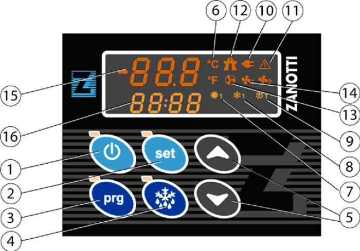
1. ON/OFF: кнопка включения/выключения рефрижератора (нажать и удерживать 3 сек). Красный индикатор на кнопке горит, когда установка включена.
2. SET: кнопка установки заданной температуры. Индикатор горит в режиме изменения температуры.
3. PRG: кнопка доступа в режим программирования (нажать и удерживать 5 сек). Индикатор горит в режиме программирования.
4. ОТТАИВАНИЕ: кнопка ручного включения режима оттаивания; нажать и удерживать 5 сек для начала цикла оттаивания.
5. ВВЕРХ/ВНИЗ кнопки изменения параметров и заданной температуры.
6. ИНДИКАТОР 0 C или 0 F: отображает единицы измерения: градусы Цельсия или Фаренгейта.
7. РЕЖИМ ОБОГРЕВА: горит при работе рефрижератора на обогрев (увеличение температуры).
8. РЕЖИМ ОХЛАЖДЕНИЯ: горит при работе рефрижератора на охлаждение (понижение температуры).
9. ИНДИКАТОР ОТТАИВАНИЯ: горит при активном цикле оттаивания.
10. СТОЯНОЧНЫЙ РЕЖИМ: показывает, что реф работает в стояночном режиме (от электрической сети).
11. ОШИБКА: загорается всегда при наличии неисправности и необходимости ремонта.
12. ДОРОЖНЫЙ РЕЖИМ: показывает, что рефрижератор работает в дорожном режиме (при включенном двигателе автомобиля).
13. ИНДИКАТОР ВЕНТИЛЯТОРА КОНДЕНСАТОРА: горит при работе вентилятора конденсаторного блока (снаружи фургона).
14. ИНДИКАТОР ВЕНТИЛЯТОРА ИСПАРИТЕЛЯ: горит при работе вентилятора испарительного блока (внутри фургона).
15. ЭКРАН: отображает текущую температуру фургона.
16. ЭКРАН: отображает наименование ошибок или заданную температуру.
Источник
Руководство по эксплуатации холодильно-отопительных установок «ZANOTTI» серии UNO


Руководство по эксплуатации

Оглавление
2. Описание панели управления в кабине……….………………..…. …….8
4. Программа планового технического обслуживания (ТО)…………. …16
5. Регистрация гарантийных ремонтов……………………………………. 21
Благодарим Вас за выбор холодильной установки ZANOTTI . Данное руководство содержит необходимые указания по правильной и надежной эксплуатации машины. Хорошее знание инструкций позволит поддерживать оптимальные условия работы холодильной машины.
Просим Вас внимательно и полностью ознакомиться с данным руководством, прежде чем запустить машину в эксплуатацию. В случае любого сомнения или замешательства просьба обращаться в нашу сервисную службу.
С целью улучшения качества продукции, ZANOTTI S.p.A. оставляет за собой право вносить изменения без предварительного уведомления.
1. Данная гарантия ограничивается по усмотрению ремонтом, заменой новыми или отремонтированными у любого уполномоченного дилера «ЗАНОТТИ ВОСТОК» деталями, которые признаны «ЗАНОТТИ ВОСТОК» дефектными при условии нормальной эксплуатации и обслуживания в течение гарантийного периода.
2. Данная гарантия распространяется только на трудозатраты и стоимость деталей. Указанные ремонт или замена являются единственным возмещением ущерба Покупателю, а устранение дефектов в проданном «ЗАНОТТИ ВОСТОК» изделии, попадающем под действие данной гарантии, упомянутыми выше способами полностью исчерпывает обязательства и ответственность «ЗАНОТТИ ВОСТОК » как на основе контракта или судебного иска (включая ответственность за халатность и/или умысел), так и на иной основе.
3. Согласно условиям Гарантии «ЗАНОТТИ ВОСТОК» любая деталь изделия, отремонтированная или поставленная взамен, устанавливается уполномоченным дилером «ЗАНОТТИ ВОСТОК» без оплаты Покупателем трудозатрат и стоимости деталей. Все замененные детали становятся собственностью «ЗАНОТТИ ВОСТОК». Такое гарантийное обслуживание выполняется исключительно уполномоченным дилером «ЗАНОТТИ ВОСТОК» и не включает сверхурочных работ, пробега автомобиля, затрат на телефонные переговоры и телеграфные отправления, а также стоимость транспортировки и/или перемещения оборудования и обслуживающего персонала.
4. Претензии принимаются только при наличии акта выполненных работ и правильно заполненного гарантийного талона, которым укомплектована установка.
5. Гарантия утрачивается в следующих случаях:
5.1. Неправильная эксплуатация оборудования (нарушение инструкции по эксплуатации, применение не по назначению).
5.2. Наличие механических, химических, термических или любых других повреждений оборудования или его узлов и (или) деталей.
5.3. Попадание воды или другой жидкости или другой жидкости на оборудование или его составляющие по причине не герметичности кузова или по любой другой причине.
5.4. Неисправность вызвана аварией, пожаром, наводнением, любым стихийным бедствием, любым другим повреждением транспортного средства.
5.5. В случае ремонта, демонтажа, монтажа оборудования лицом, не имеющим аттестации производителя оборудования или его представителя в России.
5.6. Невыполнение пунктов 9 и пункты 14 и 15 настоящих условий гарантии.
5.7. Не прохождение периодического технического обслуживания в соответствии с требованиями настоящего паспорта (и/или инструкции по эксплуатации или другого документа, имеющего отношение к данному оборудованию) оборудования.
5.8. Невыполнение любых требований, изложенных в паспорте (и/или инструкции по эксплуатации) на оборудование.
5.9. При разгерметизации рефрижераторной системы оборудования на срок более 10 (десяти) часов. Если автомобиль побывал в аварии и система рефрижератора не герметична, нужно по возможности быстро либо вновь герметизировать систему, либо заглушить технологическими заглушками соединители компрессора, конденсора, испарителя, рефрижераторных магистралей. Длительная разгерметизация приводит к попаданию в магистрали загрязнений и невозможности последующего восстановления рефрижераторной системы.
5.10. При попадании внутрь рефрижераторной системы влаги, пыли, грязи и (или) любых других инородных предметов.
5.11. При использовании оборудования не по назначению.
6. Гарантия распространяется только на дефекты, допущенные предприятием – изготовителем данного оборудования или установщиком.
7. Гарантия не распространяется на дефекты, возникшие в результате неисправности штатного электрического, механического или любого другого оборудования автомобиля.
8. Гарантийный срок на оборудование и монтаж – один год с даты монтажа (установки).
8.1. Гарантия также не распространяется на расходные материалы и материалы, необходимые для обслуживания, включая (но не ограничиваясь этим): моторное масло, смазочные материалы, предохранители, топливо, фильтры и фильтрующие элементы, калильные свечи, чистящие материалы, лампочки, хладагенты, осушители и аккумуляторы, ремни, топливная аппаратура.
8.2. Гарантия не распространяется на резьбовые элементы кронштейна компрессора, такие как: крепление компрессора к кронштейну, крепление кронштейна к двигателю, крепление деталей кронштейна между собой. Эти элементы требуют контроля в процессе эксплуатации, так как подвержены постоянным вибрациям и динамическим нагрузкам.
9. «Заказчик» предупреждён, что нормальная работа рефрижераторного оборудования возможно только в том случае, если оно установлено на изотермический фургон с коэффициентом теплопередачи через стенки, потолок, пол и двери изотермического фургона не более 0,4 Вт/м²X°С, изотермический фургон герметичен, не происходит теплообмена с окружающим воздухом через двери и (или) другие уплотнения или тепловые мосты. Температурные режимы внутри фургона, при работе оборудования, выдерживаются при температуре наружного воздуха не более 30°С, при отсутствии воздействия солнечного или любого другого излучения (нагрева) на фургон, и только при соответствии объёма и термоизоляции фургона мощности выбранного оборудования.
9.1. «Заказчик» ознакомлен с техническими характеристиками рефрижераторного оборудования и с рекомендуемыми толщинами и видами термоизоляции фургонов.
9.2. Соответствие изотермического фургона заказанному оборудованию обеспечивается «Заказчиком».
10. В случае установки рефрижераторного оборудования на фургон с несоответствующей термоизоляцией и (или) с несоответствующим внутренним объёмом, гарантийный срок на оборудование и монтаж девяносто календарных дней с даты монтажа (установки).
11. В случае неработоспособности оборудования, указанного в настоящем акте, владелец автомобиля своими силами доставляет автомобиль на гарантийную сервисную станцию и обеспечивает запас топлива, в топливном баке автомобиля, необходимый для пусконаладочных работ при производстве технического обслуживания оборудования.
12. Перегорание предохранителя не является неисправностью.
13. Запрещается снимать (отсоединять) клеммы от аккумуляторной батареи при работающем двигателе, так как это может привести к неисправности оборудования.
14. Запрещается запускать двигатель ХОУ с помощью зарядного (или любого другого пускового устройства, кроме штатного аккумулятора) устройства, во избежание повреждения электронной, электрической, механической систем рефрижераторного оборудования или автомобиля.
15. Автомобиль с заправленным рефрижератором нельзя подвергать нагреву выше 50-60°С, например сушке в окрасочной камере. При нагреве возможно аномально высокое повышение давления, что может привести к повреждению блоков и разрыву магистралей холодильной установки. Нагрев автомобиля в окрасочной камере допустим только после удаления фреона из рефрижератора.
16. При наличии, в составе рефрижераторного оборудования, блока стояночного компрессора необходимо обеспечить подачу электроэнергии качества, соответствующего нормам, действующим на территории Российской Федерации.
17. «Завод изготовитель» не несёт ответственности за любой косвенный ущерб (материальный и моральный), связанный с эксплуатацией оборудования.
Для обеспечения безопасности и поддержания бесперебойной работы холодильной установки важно, чтобы работы по обслуживанию производились с периодичностью, предусмотренной производителем (см. таблицу обслуживания).
Обслуживание и ремонт должны производиться авторизованными сервисными службами ZANOTTI.

·В случае использования холодильной машины в закрытом помещении, работать только в режиме «RETE (СЕТЬ)» (держать выключенным двигатель автомобиля во избежание отравления выхлопными газами)
·Убедиться, что между конденсатором и потолком имеется расстояние не менее 60 см и достаточный воздухообмен с наружным воздухом.
·Чистка машины осуществляется при выключенной машине и только после ее охлаждения.
·Для чистки использовать влажную салфетку с чистящим средством.
·Не использовать струю воды или пара под давлением, поскольку можно повредить электрические компоненты машины.
ДВИЖУЩИЕСЯ ЧАСТИ

·Нельзя производить обслуживание при работающей холодильной машине.
·Необходимо принимать меры во избежание самопроизвольного запуска машины.
·Во время процедуры обслуживания или ремонта, обращать особое внимание на движущиеся части, такие как вентиляторы, ремни и барабаны.
ГОРЯЧИЕ ПОВЕРХНОСТИ

·Не пользоваться холодильной машиной при открытых или снятых обшивке и панелях.
·Не засорять никоим образом поток воздуха конденсатора.
·По окончании каждого периода работы компрессор, конденсатор и трубопроводы нагнетания высокого давления сильно нагреваются. Поэтому необходимо избегать контакта с этими компонентами при ремонте или контроле до тех пор, пока они не охладятся.
·Периодически проверять, что пыль, отходы или постоянные предметы не затрудняют циркуляцию воздуха вокруг конденсатора и воздухоохладителя. При необходимости произвести чистку
УДАРЫ ЭЛЕКТРИЧЕСКИМ ТОКОМ

·Прежде чем открыть дверцу эл. щита, необходимо убедиться, что ток отключен.
·Прежде чем производить сварку на холодильной машине, отсоединить аккумулятор автомашины.
·Прежде чем производить сварку на кожухе, необходимо убедиться, что отсоединены аккумуляторы холодильной машины и автомашины, также как и генератор переменного тока.

·Убедиться, что установка электропитания имеет устройства заземления.
·Электробытовые и офисные установки должны быть соединены с холодильной машиной квалифицированным персоналом и в соответствии с нормативами.
ОБСЛУЖИВАНИЕ БАТАРЕИ
·Периодически проверять уровень электролита аккумулятора автомашины. При необходимости добавлять дистиллированную воду.
·Если батарея разрядилась, зарядить ее и проверить ток, а если она вышла из строя, то проверить соответствие аккумулятора рекомендациям по установке.
·Никогда не запускать машину или транспортное средство с помощью зарядного устройства, во избежание повреждения электронной системы холодильной машины или автомобиля.

1. ОПИСАНИЕ БЛОКА УПРАВЛЕНИЯ:
Холодильные установки серии DFZ используются для перевозки замороженной и охлаждённой продукции. Они оснащены электронным пультом управления на основе микропроцессора, который управляет работой установки в автоматическом режиме. В частности, пульт управления контролирует работу холодильного агрегата зависимости от установленной температуры. Выбор режима (дизельный двигатель или резервный привод) выбирается автоматически при включении холодильного агрегата.
ВНИМАНИЕ: Вход в режим программирования и изменение параметров работы агрегата производиться только специалистами авторизованных сервисных центров.
Любое изменение параметров влечёт за собой немедленное снятие холодильного агрегата с гарантийного обслуживания.
1.1. ВКЛЮЧЕНИЕ БЛОКА УПРАВЛЕНИЯ:
·Нажмите кнопку (ON/OFF) и удерживайте до тех пор, пока на дисплее не появится заставка ZANOTTI.
·Для выключения агрегата нужно повторить ту же процедуру.

·После заставки на дисплее появится стандартный экран.
·Функциональное назначение управляющих клавиш выводиться в нижней строке стандартного экрана.
1.2. ИНДИКАЦИЯ СТАНДАРТНОГО ЭКРАНА:


1.3. РЕЖИМЫ РАБОТЫ ДИЗЕЛЬНОГО ДВИГАТЕЛЯ:
·Нажмите кнопку  , для выбора режима работы дизельного двигателя.
 АВТОМАТИЧЕСКИЙ (START/STOP): в автоматическом режиме холодильный агрегат отключается при достижении заданной температуры и возобновляет свою работу, как только реальная температура в кузове превышает заданный лимит.
 НЕПРЕРЫВНЫЙ (CONT): холодильная установка работает постоянно без остановки дизельного двигателя.
·Нажмите кнопку  , для выбора высокой или низкой скорости работы дизельного двигателя.
ПРИМЕЧАНИЕ: Возможность выбора скорости дизельного двигателя возможна только при работе агрегата в автоматическом режиме.
ВНИМАНИЕ: В случае подключения установки к электрической сети, дизельный двигатель отключается, и установка начинает работать от резервного привода. При отсутствии напряжения в электросети режим дизельного двигателя включится через 5 минут.
1.4. ИЗМЕНЕНИЕ ЗАДАННОЙ ТЕМПЕРАТУРЫ:
·Нажмите кнопку  для появления экрана с заданной температурой.

·С помощью кнопок  выбрать новое значение заданной температуры.
·Для возврата к исходному экрану нажмите кнопку  .
.

ПРИМЕЧАНИЕ: Комбинация кнопок  в данном экране доступна только для мульти-температурных версий, и используются для выбора испарителя, температуру которого необходимо изменить.
1.5. ИЗМЕНЕНИЕ СОСТОЯНИЯ ИСПАРИТЕЛЯ:

·В стандартном экране нажмите кнопку  для перехода
в следующий экран.

·Для получения информации о состоянии испарителей нажмите кнопку  .
.

·С помощью кнопок  выберите испаритель.
ПРИМЕЧАНИЕ: Данная функция доступна только для мульти-температурных версий.
·Для изменения состояния испарителя нажмите кнопку  .
.
·Для возврата к исходному экрану нажмите кнопку  .
.
1.6. ВКЛЮЧЕНИЕ РЕЖИМА РАЗМОРАЖИВАНИЯ (DEFROST)

·Нажмите кнопку  и удерживайте в течение пяти секунд. Начало и окончание режима размораживания испарителя происходит автоматически, в зависимости от его состояния.
· Выход из режима размораживания происходит автоматически. После окончания режима размораживания установка отключается, и через некоторое время запускается снова.
ПРИМЕЧАНИЕ: Для включения режима размораживания агрегат должен работать в непрерывном или в автоматическом режиме и температура испарителя должна быть ниже +7°С.
ВНИМАНИЕ: При включении режима размораживания, в нижней части экранной панели появляется значок (DEFROST)  и начинает мигать.
1.7. ТИПЫ АВАРИЙНЫХ СИГНАЛОВ:
Существует три типа аварийных сигналов:
·УВЕДОМИТЕЛЬНЫЕ. Эти сигналы означают, что оператор должен в удобное для себя время выполнить определённые работы по техническому обслуживанию. Код можно удалить из памяти, но он будет появляться вновь, пока сохраняется причина аварийной ситуации. Наличие этих кодов не влияет на работу агрегата.
·ОТКЛЮЧАЮЩИЕ. Сигналы данного типа автоматически отключают агрегат. При их регистрации мигает значок аварий. Прежде чем запустить агрегат, нужно устранить аварийную ситуацию и удалить код из памяти. Агрегат можно включить, просто удалив код, но в этом случае вновь произойдёт аварийная остановка агрегата.
·СИГНАЛЫ ЭКСТРЕННОЙ ПОМОЩИ. Означают, что оператор должен немедленно вмешаться, чтобы предотвратить возникновение более тяжёлой аварийной ситуации. Пока код не будет удалён из памяти, на дисплее присутствует значок аварий. Агрегат продолжает работать, но некоторые функции могут быть блокированы. Код можно удалить из памяти, но он будет появляться вновь, пока сохраняется причина аварийной ситуации.
ВНИМАНИЕ: Обязательно записывайте все появляющиеся коды, они помогут специалисту по обслуживанию обнаружить причину неисправности.
1.8. ПРОСМОТР АВАРИЙНЫХ КОДОВ:
·При возникновении аварийной ситуации на дисплее появится предупреждение.
·Аварийный код сопровождается включением звукового сигнала.

·Для просмотра аварийного кода нажать кнопку  .
.

·Если зарегистрировано несколько кодов, то просмотреть их можно комбинацией кнопок 
 .
.
ПРИМЕЧАНИЕ: Наличие сигнала «ВНИМАНИЕ»  с аварийным кодом указывает на наличие активного аварийного сигнала.
1.9. УДАЛЕНИЕ АВАРИЙНЫХ СИГНАЛОВ:
·Устранив причину аварийной ситуации, нажать кнопку , чтобы вывести на дисплей аварийный код.
·Для удаления аварийного сигнала и для восстановления исходных параметров установки, следует нажать кнопку  или
или  .
.
·После удаления аварийного сигнала на экране появится надпись «No Alarms Presents».

·Для возврата к исходному экрану нажать кнопку  .
.
·Когда аварийный сигнал будет устранён, нажмите кнопку  для перезапуска установки.
1.10. ПЕРЕЧЕНЬ АВАРИЙНЫХ СИГНАЛОВ:
Тип аварийного сигнала
Неисправен датчик температуры возвратного воздуха
Отключающий
Низкое давление всасывания
Проверить уровень моторного масла (опция)
Выработан ресурс воздушного фильтра
Высокая температура охлаждающей жидкости двигателя
Открыты двери моторного отсека
Открыты двери рефрижератора (опция)
Низкое давление моторного масла
Высокое давление нагнетания
Температура возвратного воздуха вышла за верхний предел заданной температуры
Температура возвратного воздуха вышла за нижний предел заданной температуры
Не работает электродвигатель
Низкое напряжение аккумуляторной батареи
Двигатель не запускается
Неисправен датчик температуры охлаждающей жидкости двигателя
1.11. ОПИСАНИЕ АВАРИЙНЫХ СИГНАЛОВ:
·А01 НЕИСПРАВЕН ДАТЧИК ТЕМПЕРАТУРЫ ВОЗВРАТНОГО
Указывает на то, что проблема связана с датчиком или его проводкой. Этот аварийный сигнал сопровождается отключением агрегата. Необходимо устранить неисправность и перезапустить установку нажатием кнопки ON/OFF  .
.
·А04 НИЗКОЕ ДАВЛЕНИЕ ВСАСЫВАНИЯ.
Указывает, что производительность установки значительно уменьшена. Это код аварийного отключения.
·А05 ПРОВЕРИТЬ УРОВЕНЬ МОТОРНОГО МАСЛА (ОПЦИЯ).
Указывает на низкий уровень моторного масла в дизельном двигателе. Аварийный сигнал является уведомительным и не влияет на работу установки.
·А06 ВЫРАБОТАН РЕСУРС ВОЗДУШНОГО ФИЛЬТРА.
Указывает на загрязнённость картриджа воздушного фильтра. Аварийный сигнал является уведомительным и не влияет на работу установки.
·А07 ВЫСОКАЯ ТЕМПЕРАТУРА ОХЛАЖДАЮЩЕЙ ЖИДКОСТИ
Указывает, что датчик, расположенный непосредственно над водяным насосом двигателя, определил чрезмерно высокую температуру охлаждающей жидкости двигателя. Этот аварийный код сопровождается отключением установки.
·А08 ОТКРЫТЫ ДВЕРИ МОТОРНОГО ОТСЕКА.
Указывает на то, что двери моторного отсека открыты и контроллер блокирует запуск двигателя.
·А09 ОТКРЫТЫ ДВЕРИ РЕФРИЖЕРАТОРА.
Указывает на то, что открыты двери рефрижератора. Аварийный сигнал является уведомительным. Датчик открывания дверей поставляется в виде опции.
·А10 НИЗКОЕ ДАВЛЕНИЕ МОТОРНОГО МАСЛА.
Указывает, что датчик давления масла определил низкое давление масла в двигателе. Это код аварийного отключения.
·А11 ВЫСОКОЕ ДАВЛЕНИЕ НАГНЕТАНИЯ.
Указывает, что давление нагнетания хладагента чрезмерно высоко.
Это код аварийного отключения.
·А12 ТЕМПЕРАТУРА ВОЗВРАТНОГО ВОЗДУХА ВЫШЛА ЗА ВЕРХНИЙ ПРЕДЕЛ ЗАДАННОЙ ТЕМПЕРАТУРЫ.
Этот код возникает, когда разница между фактической температурой в кузове и температурой заданной превышает установленные заводские значения. Аварийный сигнал является уведомительным и не влияет на работу установки.
·А13 ТЕМПЕРАТУРА ВОЗВРАТНОГО ВОЗДУХА ВЫШЛА ЗА НИЖНИЙ ПРЕДЕЛ ЗАДАННОЙ ТЕМПЕРАТУРЫ.
Этот код возникает, когда разница между фактической температурой в кузове и температурой заданной превышает установленные заводские значения. Аварийный сигнал является уведомительным и не влияет на работу установки.
·А14 НЕ РАБОТАЕТ ЭЛЕКТРОДВИГАТЕЛЬ.
Этот код возникает в случае перегрузки электродвигателя, что влечёт за собой остановку работы агрегата от электрической сети. Аварийный код является отключающим. Для устранения аварийной ситуации необходимо обратиться на станцию технического обслуживания.
·А15 НИЗКОЕ НАПРЯЖЕНИЕ АККУМУЛЯТОРНОЙ БАТАРЕИ.
Указывает на низкое напряжение аккумуляторной батареи. Этот аварийный код сопровождается отключением установки.
·А16 ДВИГАТЕЛЬ НЕ ЗАПУСКАЕТСЯ.
Указывает на то, что двигатель пытался запуститься, но не запустился. Возможные причины: проблемы с топливом.
·А17 ПРОВЕРИТЬ ГЕНЕРАТОР (ОПЦИЯ).
Данный аварийный код возникает при работе от электропривода. Для повторного запуска, необходимо сбросить аварийный код и кнопкой ON/OFF перезапустить агрегат.
·А18 НЕИСПРАВЕН ДАТЧИК ТЕМПЕРАТУРЫ ОХЛАЖДАЮЩЕЙ
Указывает на то, что проблема связана с датчиком или его проводкой. Аварийный сигнал является уведомительным и не влияет на работу установки.
1.12. ПРОСМОТР ТЕКУЩЕЙ ИНФОРМАЦИИ ДИЗЕЛЬНОГО ДВИГАТЕЛЯ (SERVICE):
·Для просмотра текущей информации работы двигателя, стандартном экране нажмите кнопку  для перехода в следующий экран.
·Для входа в экран (SERVICE) нажмите кнопку  для появления на экране следующей информации:


·Выходное напряжение генератора
·Напряжение аккумуляторной батареи
·Температура охлаждающей жидкости двигателя
·Время работы дизельного двигателя
·Время работы от электропривода
1.13. ЭКРАН ТЕХНИЧЕСКОГО ОБСЛУЖИВАНИЯ:
·При превышении запрограммированного времени работы дизельного двигателя на дисплее появляется значок  .
.

·В стандартном экране нажмите кнопку  .
.
·Для просмотра типа обслуживания нажмите кнопку  .
.
Информация о транспортном оборудовании
Модель транспортного средства
Номер транспортного средства
ГАРАНТИЙНЫЙ ТАЛОН
Срок гарантии________12 месяцев (исчисляется с момента покупки)________
__________________заполняется четко ПЕЧАТНЫМИ БУКВАМИ__________
Настоящим подтверждаю приемку оборудования, пригодного к использованию, а также подтверждаю приемлемость гарантийных условий. Претензий к внешнему виду не имею.
Покупатель___________ Продавец___________
Программа планового технического обслуживания (ТО) транспортного холодильного оборудования ZANOTTI с прямым приводом
— Это руководство описывает операции по плановому ТО холодильного оборудования, необходимые для поддержания эффективности работы, и указывает частоту их проведения.
— Несоблюдение инструкций и порядка проведения операций согласно Программе по Плановому ТО ведёт к отмене гарантии.
— Информация о двигателе и холодильном оборудовании, указанная в Программе по Плановому ТО, позволяет определить оригинальные запчасти, что позволяет провести быстрый и надлежащий ремонт.
Программа по Плановому Обслуживанию
Интервал проведения технического обслуживания (моточасы)
Источник